DIY Foot Pedal Controller For Guitar Rig 5

DIY Modeling Software Control Pedal

Back in the old days, it took external guitar effects pedals to modify a guitar’s sound. As computer processing power has been growing at an exponential rate, software-based effects modelers have been becoming more common. [Matthew]’s dad is running Guitar Rig 5 modeling software on his Lenovo tablet. Although it works well, it is a hassle to change effects and amp models while playing. That’s where [Matthew] comes in. He’s built a foot pedal controller so his old man can change up those sweet sounds on the fly.

Guitar Rig 5 has the ability to change presets with key presses. Even so, it would still be a hassle tapping a keyboard while playing, whether it be physical or on-screen. Since an Arduino-compatible board with an ATMEGA32U4 chip can be used to simulate an HID device, [Matthew] decided to use one as the basis for his project. Standard push buttons mounted in a project box indicate to the microcontroller which keyboard commands to send to the tablet. There are 4 buttons for 4 presets on this build but any number can be used. When a button is pushed, the associated keyboard command is sent to the tablet via a USB cable and Guitar Rig 5 responds to that command by changing the preset. And just so you know where you are, an indicator light adjacent to each button shows which preset is current.

Continue reading “DIY Foot Pedal Controller For Guitar Rig 5”

Here Come The RGB LED Clones

ws2812 and clones timing

It seems like every third project on Hackaday uses WS2812 RGB LEDs in some way. We all love our blinkenlights, and bright, cheap, serial controlled RGB LEDs are the bees knees.

As with all products these days, competing manufacturers have discovered the huge market for these things, and clones are now available. [Tim] recently took a look at the PD9823, as well as three versions of the WS2812. [Tim] is considered something of a WS2812 guru here at Hackaday. You might remember him from his WS2812 driver optimization article, which should be required reading for any WS2812 hacker.

As many of us know, the timing characteristics for these LEDs can be a pain to work with. The values also differ between the WS2812S and WS2812B. [Tim] discovered that the new through hole WS2812D parts are different yet again, though rather close to the B parts. The PD9823’s designers must have studied the WS2812’s closely, as their 190ns time base falls directly between WS2812S 166ns time and the 208ns time of the WS2812B. The PD9823 also requires a slightly longer reset pulse.

The takeaway is that well written drivers such as [Tim’s] should have no problem with the new parts, but compatibility is something to keep in mind as more clones hit the market.

DIY Hydroponic System Grows Herbs On The Wall

Wall-Mounted Hydroponic Garden

Everyone knows that you should eat healthy, but it’s not always easy. Fresh and healthy foods are often more expensive than processed foods. When money is tight, sometimes it’s best to just grow your own produce. What if you don’t have room for a garden, though?

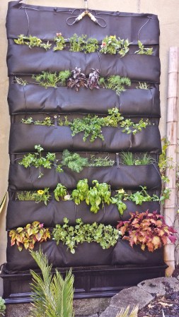
When [Matthew] returned home from the 2014 San Mateo Maker Faire, he found himself in a similar situation to many other faire attendees. He saw something awesome and was inspired to build it himself. In this case, it was a wall-mounted hydroponic garden. [Matthew] started out with some basic requirements for his project. He knew which wall he wanted to cover with plants, so that gave him the maximum possible dimensions. He also knew that they may have to remove the garden temporarily to perform maintenance on the wall in the future. And as for what to grow, [Matthew] loves lots of flavor in his foods. He chose to grow herbs and spices.

[Matthew] purchased most of the main components from Amazon and had them shipped to his doorstep. Everything else was found at the local hardware store. The base of the build is an off-the-shelf planter box. The drainage hole in the bottom was plugged up to prevent water from leaking out. A different hole was drilled in the side of the box to allow a garden hose to be mounted to the box. The hose is connected through a float valve, keeping the water level inside the box just right.

[Matthew] then built a frame out of dimensional lumber. The frame ended up being about 4.33 feet wide by 8 feet tall. The boards were fastened together with metal braces and mounting plates. A full sheet of plywood was then nailed to the front of the frame. Thick plastic sheet was then wrapped around the frame and stapled in place.

[Matthew] purchased giant planter pockets to actually hold the plants. He tried stapling them to the front of the frame, but discovered that staples were not strong enough to hold the weight of the plants, soil, and water. He instead used screws and washers.

Next, a submersible pump was mounted inside the bottom planter box. This pump is used to circulate the water and nutrients up to the plants above. Two hoses were connected to the pump and run up the sides of the upper frame. These hoses evenly distribute the water to the plants.

The final step was to mount the unit in place against the wall. [Matthew] didn’t want to screw into the wall and cause any damage. Instead, he placed a couple of bricks inside of the planter box and rested the bottom of the frame on top of those. The top of the frame is essentially hung from a railing up above with some thin steel wire.

The whole unit looks very slick and takes up little space. With some more ingenuity, one could likely build something similar with even more DIY components to save some more money.

Hackaday AMA: Thursday Morning At 10am Eastern Time

hackaday-szczys-reddit-proof_1Come one, come all, to an epic Reddit AMA.

It’s been almost two years since our last “Ask Me Anything” and it’s an understatement that ‘sort of a lot has happened’ since then. We changed parent companies, expanded our writing staff, hosted our first live event (and a few smaller ones since), launched Hackaday Projects, and now we’re in the middle of The Hackaday Prize.

Any question is fair game (that’s why they call it an AMA) so now’s the time to get that query that’s been bugging you answered.

You will need a Reddit account to ask questions or to vote them up and down. But anyone can read the thread without logging in. Speaking of threads, we can’t give you a link yet because it won’t be available until we start at 10am Eastern Time on Thursday, June 26th. But watch the top of the blog, we’ll publish another post as soon as the link is ready!

UPDATE 6/26/14 9:25am Eastern: The Reddit thread is now live. Please feel free to start adding questions. Answers will start in 35 minutes.

Retrotechtacular: Kodak Built World’s First DSLR… Using A Canon Camera Body

worlds-first-dslr

It has been far too long since we’ve seen an installment of Retrotechtacular, and this is a great one to start back with. It’s always a treat to get the story from the horse’s mouth. How about the tale of the world’s first Digital Single-Lens Reflex camera? [Jame McGarvey] shared the story of how he developed the device in 1987.

That’s it shown above. It’s not surprising to see that the only real modification to the camera itself is the back cover. The difference between an SLR and a DSLR is really just the D, which was accomplished by adding a CCD in place of the film.

The entire story is a treat, but there are a couple of nuggets the we enjoyed most. The possibly-clandestine purpose of this device is intriguing. It was specifically designed to pass as a film camera which explains the ribbon cable connecting the CCD module to the control box which would be stored in a camera bag. It is also delightful to hear that the customer who tasked Eastman Kodak with developing the system preferred Canon camera bodies. So this Kodak DSLR indeed used a Canon F-1 body.

Once you get done looking this one over you will also enjoy learning how a CCD actually works.

[Thanks Ben]

Retrotechtacular is a weekly column featuring hacks, technology, and kitsch from ages of yore. Help keep it fresh by sending in your ideas for future installments.

THP Entry: Making Amateur Astronomy Easy

explrad 
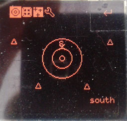
With the advent of electronics in everything, amateur astronomy has never been easier. Telescope mounts that point in the direction of any astronomical object automatically have been around for decades, and the Telrad – a device that paints 0.5, 2, and 4 degree diameter circles in your finder scope’s field of view are available if you’re just too cool for letting a robot do your job. [Christoph]’s explorad takes the concept of a Telrad and adds a somewhat more electronic twist: it still displays the field of view circles, but adds highlighting of interesting astronomical objects from a custom telescope mount, a huge database, and a few sensors.

By far the biggest challenge to any homebrew finder of astronomical objects is figuring out where the observer is. Not only does [Cristoph] need to take into account the location on Earth (GPS helps with that), but also where North is (electronic compass), where the telescope is pointing (optical encoders on a two axis mount), but also the universal time and current sidereal time. Living on a rotating planet that orbits a sun makes for a lot of code.

The current progress on the star finder to beat all star finders is a bit of code that draws the ‘telrad circles’ and displays placeholders for each patch of sky with a small triangle. Tilting the device or turning the azimuth pot moves these triangles and loads new ones on the fly. Now the name of the game is a sky object database for all the astronomical objects [Cristoph] wants to view.

Programmable Logic II – CPL

There is a wide assortment of cheap development (dev) boards for Complex Programmable Logic Devices (CPLD), the smaller cousin of the Field Programmable Logic Array (FPLA)

Using an inexpensive board and the development software that’s free to download from the major programmable companies such as Xilinx and Altera, the only additional thing needed is a programmer module. Cheap ones are available on Ebay but I am hoping that someone takes the time to teach an ARM/Arduino to step in as a programmer.

I have a small collection of dev boards including some Ebay specials and also designs I did a few years ago to choose from. For today I am grabbing a newer board that has not been fully checked out yet; an Altera Max V device. I have stuffed the CPLD, the clock oscillator, some LED’s and part of the onboard power supply along with the JTAG header needed to program the CPLD and that’s about it.


Herdware CPLD 5M570ZT
Herdware CPLD 5M570ZT dedicated PCB with SRAM.


CPLD Schematic
CPLD Schematic showing an Altera CPLD 5M570T144

Continue reading “Programmable Logic II – CPL”