I became aware of harmonics and the sound of different shaped waveforms early in my electronics career (mid 1970’s) as I was an avid fan of [Emerson Lake and Palmer], [Pink Floyd], [Yes], and the list goes on. I knew every note of [Karn Evil 9] and could hear the sweeping filters and the fundamental wave shapes underneath it.
I remember coming to the understanding that a square wave, which is a collection of fundamental and (odd) harmonics frequencies, could then be used to give an indication of frequency response. If the high frequencies were missing the sharp edges of the square wave would round off. The opposite was then true, if the low frequencies were missing the square wave couldn’t “hold” its value and the top plateau would start to sag.
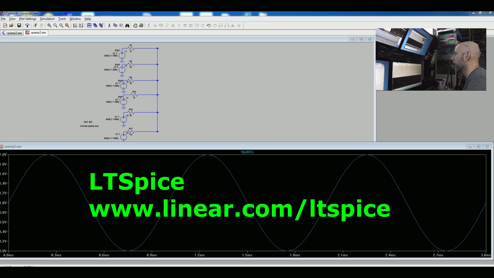 Using a copy of [SPICE] a free circuit simulation application, I have created several sine wave sources and summed them together. Seen here, the waves combine into a square wave with it looking squarer as I add more and more signals that are multiples of the main frequency called harmonics. When building a square wave only odd harmonics are used as even harmonics tend to cancel themselves out.
Kno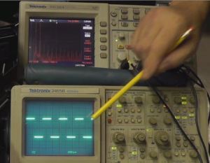 wing now that we can build a square wave from multiple signals it then stands to reason that we can take a waveform apart and display its constituent pieces or signals.
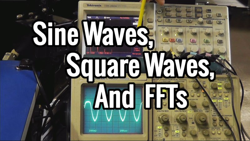
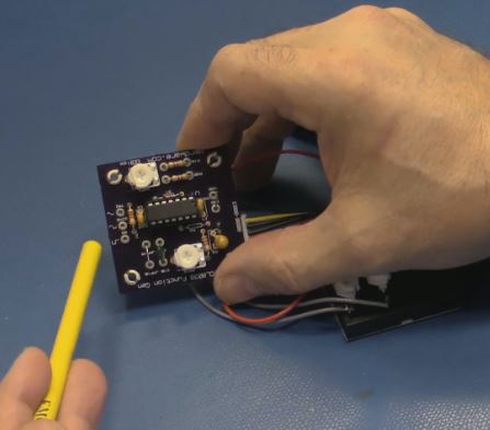
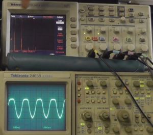
Enter the Spectrum Analyzer; In this case it’s some math that occurs in my Digital [Tektronix] scope in the form of a Fast Fourier Transform (FFT). For this demonstration I left the 102 pound [HP] RF Spectrum Analyzer in its nook below the bench.
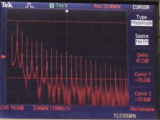
Sure enough, the odd harmonics stand out right where they are supposed to be. I could lay a small ruler touching the tips of the waves and they form a straight line. This is possible as the display itself has already been converted to a logarithmic scale.
My inclination is to launch into a diatribe of how these frequencies, always higher than the fundamental, combine to create noise in the RF Spectrum and how the interaction of these waves also get caught up in transmission lines, ground planes, apertures and antennas. Instead I will go back to my roots and put the signals to a speaker so that they might be heard. It’s easy to hear a note from [ELP Lucky Man] and when listening carefully one can start to equate sine wave distortions with “spray” or the extra harmonics that give some depth to a note being played on a synth. Play around with this. Who knows, maybe you’ll end up getting the band back together?


Awesome, at work right now but I can’t wait to watch this!
When I connect my oscilloscope to various ham radio projects I can see… nope, not quite getting the clean sine wave I expected. But.. then what? I haven’t found any guide to explain what kinds of distortions create the flaws I see in the pattern on the scope.
I’m hoping this video contains the answers!
It could be real, measurement artifacts, or both. Your probe, especially a passive one, has an impedance that affects the circuit you’re measuring. Also the probe ground can be a ground loop path through the power supply and the scope’s AC supply.
I’m waiting til later to watch the video too. At least I can scratch the itch to listen to Brain Salad Surgery on Spotify right now.
Brilliant.
Listen up people! Converting audio and video from the time domain to the frequency domain by using Fast Fourier Transforms (and lossy compression by removing information that you can’t see or hear anyway, from the frequency domain version of the signal) is basically how almost all digital media works nowadays. MP3, TV, Phone, YouTube, JPEG etc.
It’s hard to believe that it’s less than 20 years ago that an average PC couldn’t even do FFT and compression fast enough to encode an MP3 file in real-time. It’s a great time to be alive.
’tis that.
I love living in the future. Now, where’s my flying car!
You are so right, The computing power that is behind all devices D to A conversion is simply amazing! I feel lucky to be old enough to have witnessed and experimented in this time of change. Kid’s toys create some very unique complex sine waves when circuit bent. :)
Do FFTs account for phase, or do they only do frequency?
And my kingdom* for a lucid explanation of wavelets/chirplets.
(*A gourmet lollipop and spare tube of flux.)
A full FFT produces a complex number, so yes, phase is included. Fourier, the mathematician, told us that any waveform can be expressed as a sum of sine waves of varying phase and frequency. A square wave takes an “infinite” number of them. So, wavelet transforms were developed to use discrete pieces of a sine wave to reduce the amount of information you need to describe the signal. They’re more useful for impulse reponses as compared to Fourier series.
I’m familiar with impulse responses, so that’s a good explanation for me.Thanks! =)
I used to have to decode my MP3s to WAV, then record them onto cassette tape! One at a time of course, not enough disk space for more than a few WAVs.
This was just about the time before WinAMP came out. I still have the early MP3s, and listen to them on my phone. They sound terrible!
Ah, the memories. I remember waiting 20 to 30 minutes for an MP3 to record. And then using two computers, one to play music, the other to do work because the first could barely handle the load.
I collected so much more music back when it was hard. It felt more rewarding. Now don’t bother and just listen to Pandora 90% of the time.
I only remember what happens when an audio amplifier is pushed to the point of clipping, creating flat tops, and it contains a lot of the harmonics of a square wave. When that happens, if your amplifier amplifies them, they could destroy the tweeters. I don’t know if modern amplifier design has found a way to deal with, but I did see more than a few blown tweeters in my days of selling high ends amplifiers and speakers.
My home theatre receiver shuts off the output if it detects excessive (read as destructive) distortions in the signal. Took me a while to figure it out until I saw how my son plugged in his game and cranked the signal up to OH MY DEAR LORD GOD ARE YOU TRYING TO WAKE THE DEAD?
Is that past 11?
One of the things that this shows is how to generate multiples of a sine wave. Take a sine wave of frequency F, run it through an overdriven amplifier to clip it. The output will have all of the odd harmonics. Then filter out for the one you want.
This is how the local oscillators for most microwave band radios work. You don’t create a 9Ghz oscillator, you multiply 333.33Mhz 27 times and filter.
Used to be. Now, you buy a chip that is a combination 9 GHz oscillator and a PLL :-)
YIG sources were also commonly used, as multiplied oscillators often had phase noise problems.
Bit back to basics:
A square wave is a series of sine waves <<< not true
A square wave can be described as a series of sine waves << true
It only depends what you take as your basis function.
A sine wave can be described as a series of square waves << true
The distinction between “is” and “can be described as” is a bit artificial. A square wave IS a summation of sine waves, in the same sense that 12 is the product of 2*2*3. Yes, there are other ways to describe 12. It’s 10+2, or 36/3, or the square root of 144, among infinite other descriptions. But converting an integer into its prime factorization is a canonical and often useful way to describe the integer. Likewise, there are many ways to describe a repeating waveform. But describing it the way Fourier did it, as the weighted sum of a sequence of harmonically-related sine waves, is a canonical and very useful description.
The point I was trying to make is that any wave shape can be made from a series of any other wave shape. The convenient use of the definition leads a lot of people to believe that it is a fact that square waves are made from sine waves and that is not true, they can be described by a series of sine waves.
It is actually a quite hard concept to grasp until you learn the theory but I think that it should be explained as above from an early stage in education even if the why of it is not covered at that time.
John, it is true that a square wave in the real world is the sum of a series of sin waves. To change the intensity of a signal in 0 time requires infinite energy.
The infinite power bit is right but the square sine thing is not right, it simply isn’t true.
Bill, a side benefit of the physics of “square” waves I’ve noticed is the (9%?) overshoot you get gives you more room for level latching. For example a 5V part may need 3V for a logic high, and <2V for low. Some "experts" tried to tell me a 3.3V input would only give you a 10% margin of error, but the harmonics will peak at 3.6V, or 20% over the required 3V.
Of course the ringing will also bottom out around 3V, but that's still well above the hysteresis limit for the logic low.
http://en.wikipedia.org/wiki/Gibbs_phenomenon
The technique of pre-emphasis and de-empahsis modifies and enhances this effect so that waveforms look like square waves then they reach their destination after having traveled through a long or noisy path. Great gains to data rate are made.
Emerson’s solo on ‘Lucky Man’ is like a dissertation on signal processing that is also a beautiful work of art. Always enjoy your articles, Bil.
Extra credit for anyone who knows what happens to the “square” wave when you don’t have an infinite number of harmonics (i.e. odd frequency components).
Well, as luck would have it, I just read this somewhere today:
‘If the high frequencies were missing the sharp edges of the square wave would round off. The opposite was then true, if the low frequencies were missing the square wave couldn’t “hold” its value and the top plateau would start to sag.’
I studied this in an academic setting and knew about the odd harmonics and some of the math. But I wouldn’t have had a gut level feeling for what I was seeing if I looked at a “defective” square wave on a scope.
Actually, you get overshoot called the Gibb’s phenomenon, https://en.wikipedia.org/wiki/Gibbs_phenomenon. It never goes away until you get an infinite number of harmonics. It’s hard to get to infinity. Fourier series are wonderful and fascinating.
The square has funny wiggles on the edges — roughly corresponding to the highest-frequency of sine wave that you’re using.
“Gibbs phenomenon”
FFTs in midrange scopes piss me off to no end, many of them do not show the frequency per dev or let you set it really
so many words
https://www.youtube.com/watch?v=oafoTUU91hU
https://www.youtube.com/watch?v=6RxSKh0c_jI
The mind blowing thing is that to create a squarish wave pulse the harmonic waves have to start before the initiation of the pulse. In other words electromagnetic waves are created in the past, present, and future.
If you’re interested in the topic, Richard Feynman wrote about the time invariance of quantum mechanics, like there being no difference between an electron going forward in time and a positron going back in time.
TLDR, All I got out of it was an A to D converter….