To say that the RTL-SDR project was revolutionary might be something of an understatement. Taking a cheap little USB gadget and using it as a Software Defined Radio (SDR) to explore the radio spectrum from the tens of megahertz all the way into gigahertz frequencies with the addition of nothing more than some open source tools may go down as one of the greatest hacks of the decade. But even in the era of RTL-SDR, what [Ted Yapo] has manged to pull off is still pretty incredible.
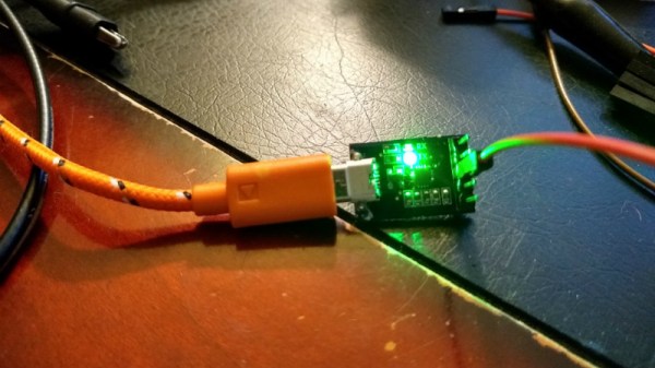
With a Python script, a length of wire attached to the TX pin, and a mastery of the electron that we mere mortals can only hope to achieve, [Ted] has demonstrated using a common USB to serial adapter as an SDR transmitter. That’s right, using the cheap little UART adapter you’ve almost certainly got sitting in your parts bin right now and his software, you can transmit in the low megahertz frequencies and even up into VHF with some trickery. The project is still very much experimental, and though this may be the first time, we’re willing to bet this isn’t the last time you’ll be hearing about it.
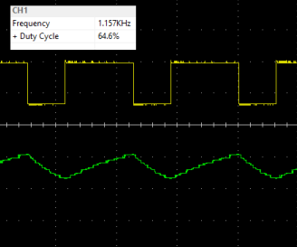
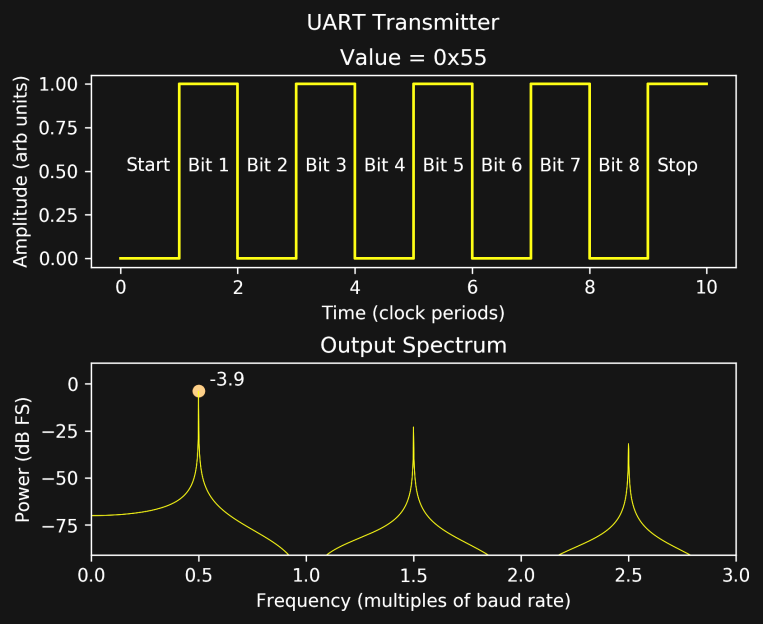 The basic idea is that when sending certain characters over the UART serial line, they can combine with the start and stop bits to produce a square wave burst at half the baud rate. [Ted] found that sending a string of 0x55 at 19200 baud would generate a continuous square wave at 9600 Hz, and if he turned the baud rate all the way up to 2,000,000 where these USB adapters top out, that signal was transmitted at 1 MHz, right in the middle of the AM dial.
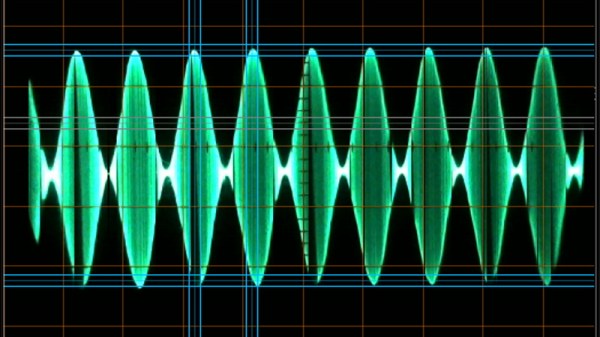
A neat trick to be sure, but alone not terribly useful. The next step was to modulate that signal by sending different characters over UART. [Ted] explains at great length his experiments with multi-level quantization and delta-sigma schemes, and each step of the way shows the improvement of the transmitted audio signal. Ultimately he comes up with a modulation scheme that produces a impressively clean signal, all things considered.
This alone is impressive, but [Ted] isn’t done yet. He realized that this method of transmission was generating some strong frequency harmonics which extended far beyond the theoretical maximum 1 MHz frequency of his UART SDR. In his experimentation he found he was able to pick up a signal from all the way out to 151 MHz, though it was too poor to be of any practical use. Dialing back the expectations a bit, he was able to successfully control a cheap 27 MHz RC toy using the 43rd harmonic of a 631 kHz signal at a range of about 10 feet with a FT232RL adapter, which he notes produces the cleanest signals in his testing.
[Ted] is still working on making transmissions cleaner and stronger by adding filters and amplifiers, but these early accomplishments are already very promising. His work reminds us of a low frequency version of the USB to VGA adapter turned GHz SDR transmitter, and we’re very eager to see where it goes from here.
Continue reading “Your USB Serial Adapter Just Became A SDR” →

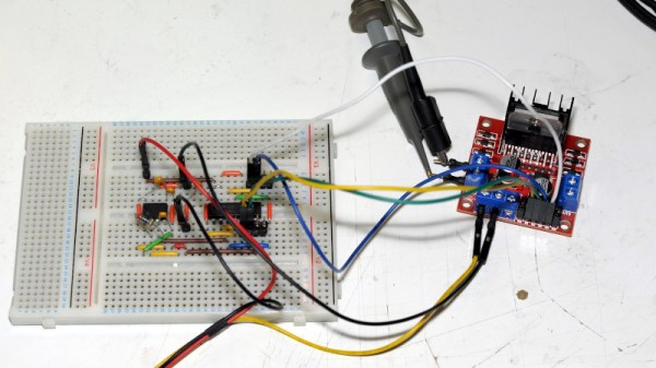
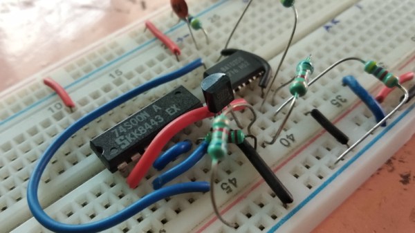
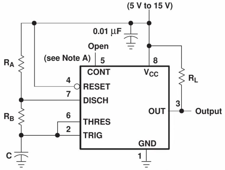 As beginner videos go this one is fairly comprehensive. [Andrew] shows us how to build a square-wave generator on a breadboard using a 555 timer, explaining how its internal flip-flop is controlled by added resistance and capacitance to become a relaxation oscillator. He shows how to couple a potentiometer to vary the frequency.