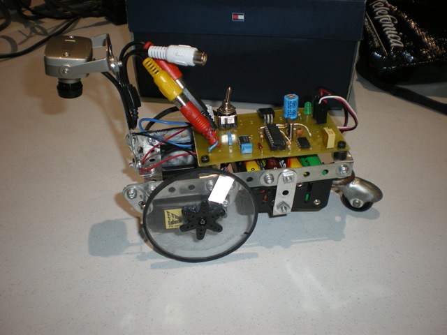
There are quite a few flavors of line following robot. No matter how they’re made, most are built for speed and accuracy. The Cambot by [Jorge Fernandez] however makes use of a traditional video camera to read visual input instead of the reflective sensors we’re used to seeing in these types of robots. Because of this it lacks those swift and agile qualities, but scores points with its unique analog design, over-sized tricycle wheels, and stylish RCA jacks poking out on the side.
Coupled with a PIC 16F84A microcontroller, [Fernandez] divides the video input from the camera into 625 lines. The PIC is responsible for scanning horizontally across these lines and translating the proportions of black and white into PWM pulses. The duration these proportions are seen by the camera determines the PWM frequency fed to the left and right servo motors driving the robot.
As far as line-followers go, this is a refreshing retro approach to the concept. [Hernandez] outlines the finesse about driving his cambot on his blog (an English translation can be read here) and provides a complete schematic for those who are interested in whipping up their own quirky little machine.


An old project, but still a good news. Buen trabajo omega! :D
I’m curious why he has sound plugged in. And why the right side?
That looks like the power supply for the camera. Now a good challenge would be to try to do the same with analog and discrete logic in place of the PIC…
Yes that would be really impressive. Probably pretty large, too.
That’s kindof what I thought it was from the title.
It would be nice to put the steering closer to the camera – so the point of rotation may stay slightly tighter to the line recogition – and less jerky navigation. Nice work.
Analog? PIC! Picky Picky Picky.
If I can hear the video signal I can focus perfectly, blindly on a high contrast text card. Focusing causes the buzz to have the most zing. I should able to hear the drift of a big line running in the horizontal direction. It will be a phase shifting sound at frame frequency.
Apply phase determining in reference to the vertical sync.
Where did he source the camera from? I could use a cheap NTSC version.
Looks like one of those cheap “spy cams” more often marketed as an aftermarket backup camera.
Thanks for the tip.
Little hint: often colour cameras can be hacked by removing the crystal and replacing it with one exactly half the frequency.
This allows for slower frame rates and higher fidelity (more integration time for the sensor) so often even a crappy el cheapo CMOS can be used for this.
I came up with this technique while experimenting with X-ray and alpha imagers and tried it recently on a colour camera, although the picture looked a little strange on my ‘scope it did show the method works.
A 7.2 MHz xtal can be found in many old electronics such as answering machines, obviously 8MHz is another common value.
I found that if the camera is fussy about working with the wrong crystal this can be fixed by changing out the parallel capacitors for slightly higher (ie 33pf) capacitors.
Even managed to get it running at 1MHz averaging under 6 frames per second.