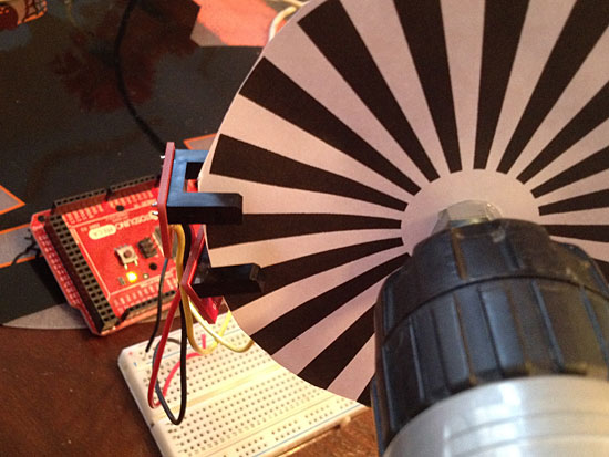
[Pete] needed a rotary encoder for one of his project so he set out to build his own. As the name implies, a rotary encoder measures rotation by encoding “steps” into electrical signals which can be measured by a microcontroller (or used in numerous other ways). Knowing the degrees of movement for each step will allow you to calculate precise distance traveled in applications like robot wheels. Or you can simply use the rotating shaft as an input device which navigates menus or settings.
This concept is a good one to understand. We had originally planned to build rotary encoders for the multi-person Duck Hunt at Hackaday’s 10th Anniversary but the build-off crew had difficulty getting the system to work. In [Pete’s] case he’s using photointerrupters (apparently the IR beam is easily detected through the white paper but usually these parts would be cut out of the disk). We were using reflectance sensors. Either way there’s a trick to detecting which direction a rotary encoder is turning. We’ll explain that for you after the break.
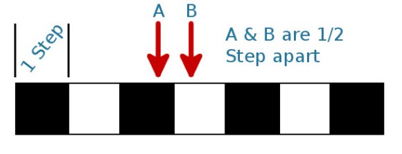
For ease of understanding we’ve straightened out the encoder wheel to this line of white and black boxes. Each one is a single step of the encoder. To measure direction you need two sensors; a single sensor would detect the same pattern of white and black boxes no matter which direction it was turned.
The two sensors are mounted “out of phase”. They are exactly 1/2 of a step apart. If you look at the image right now, sensor A detects a black box, sensor B would register a white box. Because they are 1/2 step apart, they will never change state at the same time. It will always be one after the other no matter which way the pattern moves.
As long as the current state is known, the next sensor to change will denote the direction the encoder pattern is moving. If you move the pattern itself to the right (the sensors are stationary) the next thing to happen will be sensor B going from white to black. But if you move the pattern to the left, the next thing to happen will be sensor A going from black to white. The pattern of outputs is known as Gray Code and can be parsed using a look-up table or with simple logic.
This concept is exceedingly simple if you take the time to boil it down to the core concept and work through what exactly is happening as we have here. That’s the case for most hardware concepts, and it’s well worth seeking out and digging into areas you don’t totally understand. It makes magical and mysterious sensors like magnetic rotary encoders easy to understand.


It should also be noted that this is called a quadrature encoder configuration. The Sensor will give 4 pulses (be it “A” or “B”) for each “step” of the encoder disk.
I bough some cheep rotary encoders with a press switch as that’s enough for a simple mcu menu system.
When I wrote the code for it I found that sometimes the encoder would miss a pulse and that created a very annoying reverse step with the code I wrote. I fixed the code to ignore missed steps rather than going backwards. It was a pain to code as you also have to worry about contact bounce with these types of switches.
In hindsight it would have been much easier to write the key bounce as a separate routine and then use a state look up table like has been done here.
1 bit for the previous direction, 2 bits for the previous state, 2 bits for the current state – an index of 0 to 31 in a lookup table would be much easier.
Each to their own, but I don’t see the point in debouncing in software when a simple capacitor on each contact works perfectly.
Because you then don’t need a capacitor, or the time to solder it, or the space to fit it in. Plus it’s trivial to do.
I could say “Each to their own, but I don’t see the point in using capacitors when I can use double-throw switches!”…the best debounce systems usually use a hybrid of the software & cap approaches, with some careful switch selection…but in most cases, the internal micro’s debounce (if so equipped) is entirely accurate.
Then again, for a safety-critical system or other things, sometime you need the more exotic methods beyond just RC filters…
Well it’s moot anyway, since we are dealing with optical sensors, which do not bounce.
I did it this way as a programming exercise for these encoders so including software debounce was helpful. It was probably good that I chose this method to start with as it made me aware of the missing pulse issue with these cheap encoders.
I didn’t use any RC filtering because I just soldered three wires to the switch and plugged them into GPIO of the development board. I also used port polling instead of interrupts.
This method is probably fine if your happy to use port polling but I would be inclined to add CR filtering if you want to use interrupts. The board real estate and a couple of passives is no big expense.
Also in my first post I should have said 2 bits for previous direction state to include the missed pulse condition.
You don’t need to do debouncing with a quadrature encoder, as long as only one of the two sensors can bounce at the same time. In other words, you can bounce between states 0-1, between 1-2, 2-3, and 3-0, but never between 0-2 or 1-3.
Yes agreed but if a pulse is missing here’s how your system responds –
transition 0 – 1, state now 1
transition 1 – 2 is missing
next transition is to state 3 but it is ignored as the previous registered state was 1
transition to 4 – this is accepted but is in the opposite direction to the actual rotation.
Apart from that the mechanical wiper switches are prone to noise so I still think debounce is a good idea.
With debounce and registering the last know direction as well as state you miss one forward pulse which is only half as bad as registering a false reverse step. The human factor will correct for this. The down side is that a reverse in direction takes one extra step to accepted.
I would consider a sensor faulty, if it suffers from missing pulses, or bounces on both contacts at the same time. It’s going to be unreliable no matter what.
the next sensor to change will denote the direction the encoder pattern is moving.
As long as that change is to a different color. If the next change is to the same color, that’s the trailing sensor.
If you are decoding with digital logic there are a couple other tricks that may help. You can connect A or B to one input on an 7486 XOR gate and the same A or B through a resistor to a 7414 Schmidt Trigger NOT gate. Also connect a 20 pF capacitor between the NOT gate input and ground. The output of the NOT gate connects to the other input on the XOR gate. This causes a short delay on that input to the XOR gate. The two XOR gate inputs will be different during the delay causing a short pulse output. This is good for triggering a flip flop or microcontroller interrupt. If A = B when the pulse is finished and A triggered the pulse you know the encoder is turning one direction. If A = B when the pulse is finished and B triggered the pulse you know the encoder is turning the opposite direction. A quick calculation shows that you will get about 20 nS pulse on the rising edge of a TTL logic if you use a 3.6K resistor and a 20 pF capacitor. It will be a little longer on the falling edge.
Take a look here:http://www.dghacks.com/micro-controller/quadrature_encoders/
There is a good article about how to get past things like missing pulses. It also has example softwre
Overly complicated, though. When you look at the ALPS encoder, you see that it has detents (it clicks) on state 0 and 2, but there are no detents in states 1 and 3.
The trick is then to only adjust the position counter at the detents in state 0 or 2. At any other time, just save the state, but don’t change position counter.
When state goes from 0->2, check previous state. If it was 1, the encoder went clock wise 012. If it was 3, it went counterclockwise 032. When state goes from 2->0, you do the reverse.
No need for debouncing logic or analog filtering.
That’s the algorithm used in the linked article, if you dig through the code, and it basically amounts to only testing for direction when “sensor A” changes.
You lose half the resolution relative to updating when either sensor changes state, but you certainly gain in robustness.
It’s similar in concept, but the implementation is more complex. It does debouncing first, and then it uses a lookup table to determine if the state change is legal.
Here’s my code:
state = get_encoder() ^ toggle;
if (state == 0)
{
toggle ^= ENC_A | ENC_B;
if (previous & ENC_B)
position++;
else
position–;
}
previous = state;
The get_encoder() function returns two encoder bits, ENC_A and ENC_B (can be arbitrary bits). The code waits until both encoder bits have toggled, and then updates the position.
@Elliot Williams I have used the code from there and it does not lose half the resolution. It also solves the problem that the one detent is on a change point so if you just touch the decoder it switches
The ALPS switches behave in a sane way. One detent equals two state changes, so you get exactly the resolution you want.
You can also look at my blog: http://heliosoph.mit-links.info/photointerrupter-basics/ This is the start of a series about rotary encoders. It goes from the beginning (using a photointerrupter) until making a quadrature encoder all together with some arduino code examples.
Here is something usfull, if you want to build for cheap:
http://www.webx.dk/oz2cpu/20m/encoder.htm
That’s a great idea if you need one in a hurry. Using an old stepper motor and parts out of an old printer/floppy you can get 200-400 steps/rev stock(even more based on poles). You don’t even have to get crazy with voltage regulation, you just need to build a zero point crossover detection circuit with 2 op-amps. Similar to that of a variable reluctance sensor The only downside is it’s a little bit heavy and you will get some minor detent torque on the drive shaft, but otherwise quick and simple.