Many CPU-usage widgets have stylistically borrowed from vehicles, displaying something mimicking the tachometer found in the dashboard. [Pat] took it a step further and tried his hand at re-borrowing this style. He figured, why not use an actual physical tachometer to display how hard the CPU on his Raspberry Pi was revving?
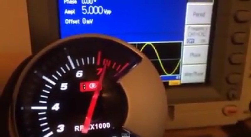
With the goal of tuning 0-100% CPU usage to 0-8000 RPM on the tach, the first step was diagnosing the range of PWM input frequencies that moved the needle across the tach’s full arc. Using his Tektronix 3252C function generator he quickly determined 0-440 Hz would be needed and graphed a handful of intermediate points. The response curve was not linear, so he drew up some fudging guidelines to make all the datapoints match.
Next, he wrote a few lines of Python (he shared) to make the Pi to poll its CPU usage and translate it to the proper frequency. The Pi makes outputting easy, GPIO pin 11 carried the signal to a 7404 for buffering, then out to the tach. The automotive tach itself ran on 12V, but its input signal required only 5V so he pulled a 7805 from his parts bin.
Once it was all put together it worked beautifully using just the one extra component. Some might see this as more clever than USB dependent or Arduino bloated based tachometer hacks.
See the video after the break of the tach twitching even when the mouse moved, and pegging the red when opening a browser. No more need to use up valuable screen real-estate (or use a screen at all) if you want to see at a glance when your Pi is putting in work.
If you were hoping for a device that adds a tachometer to display actual RPMs of something, we have covered that before too!


The Tacho is a linear devive, but the input signal has to be right….
The early tachos took a signal off the ignition, so it got a very short pulse.
Later units take a pulse off the crankshaft…
if you drive it from a square wave that has a mark space ratio of 50:50 it will read incorrectly
it expects a short pulse, which it expands by a set amount, then averages this before sending to the meter, a pulse too long will give issues.
Your post got me thinking. I have a truck with a rebuilt 1972 engine, and for some reason the signal from the ignition ends up killing even expensive tachometers after about a year. I wonder if there’s a voltage issue, and the newer tachs need a lower voltage on the signal line to keep from dying? Maybe I can do what [Pat] did and use a voltage regulator inline on the signal line.
I’m trying to turn some SV650 clocks into a set of power/gas usage meters. I found the Speedo to be easy. 5V straight from the Arduino (don’t worry purists, it’s just to reverse engineer the thing for now) and the PWM library. Sorted (It’s 1Hz ≈ 1mph btw). The Tacho gets its signal straight from the ignition circuit according to a diagram. On a forum someone measured the signal coming from the bike and saw up to 100V spikes in the supposedly 12V signal. So older vehicles ignitions can pump out some crazy voltages. I’m still struggling with that tacho.
Maybe on modern tachs- but for the longest time, tachs were just DC meters connected to a capacitor, functioning as a crude high pass filter that indicated higher when the ignition pulses occurred faster. There was no fussy circuitry worrying about the duty cycle. Natrually accuracy was very limited.
Other old tachometers were mechanical, basically a speedometer, but instead of being attached to the output of the transmission, were connected to the engine (crankshaft, camshaft?, distributor?) The “odometer” portion of the tachometer was the Hour meter. But the Hour was only correct at a specific RPM (less than that, the “Hour” was longer)
hehe, the ReCoMonB project started this way http://www.ivancreations.com/2013/07/real-computer-monitoring-block.html
This project has inspired me to build a whole instrument cluster to put on my desk. Tach for the CPU, speedometer for network bandwidth, fuel gauge for HDD space, etc…
“No more need to use up valuable screen real-estate (or use a screen at all) if you want to see at a glance when your Pi is putting in work.”
Yeah cause that would be Accurate, Convenient, Easy, Built-in, Way less stupid looking, did I mention ACCURATE, etc.
In other words, this is a great hack!
I’ve always wanted to do this on my main PC, but I can never find a cheap tachometer… I would also prefer one that goes to 10k rpm, just so it’s an easy mental conversion. I guess you could also use any analogue gauge and print a custom face…
Seems like I’ve seen this before.
For the full experience send the tach signal to a v8 cooling fan.
Awesome.
FYI there is a little used LOAD guage for internal combustion engines. The Tach might be a good idea for your processor speed, maybe Giga-cycles per second? in that case a Diesel based tach with a redline of 4-5 might be prudent.
Since a Raspi can have (maybe) 1 Gigacycles, not useful.
The load guage is actually a fuel-consumption guage, higher load, more fuel consumption, as I said, rare in a physical guage. Slightly popular in the 70s when gas crises and muscle car crossed paths. Or in my case a late-80s BMW that had a “fuel economy” guage.
since these guages usually were just a vacuum guage I’m not sure how to accurately drive them from a PC
To drive it from a PC you’d probably need a Celeron, it sucks! B^)