[Nick Sayer] falls into the “would rather build it than buy it” category. This particular project is a clone of a fast electric vehicle charger. There are commercially available versions sold under the Quick 220 brand name. The idea is that for fast charging, some electric vehicles call for a 240V outlet and Americans without electric cars often don’t have one. If they do it’s for an appliance like a stove or clothes dryer and probably not found in the garage.
The device uses two hot and one ground to supply the 240V output which is, in some business where there is three phase power this will be closer to 208V but should still work. Obviously you shouldn’t be doing this unless you know exactly how it works, and we applaud [Nick] for airing these hazards while at the same time supplying the knowledge behind the concerns.
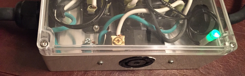
Two inputs for the beefy converter are supplied from outlets not just on separate circuits, but on two circuits whose hot lines are 180 degrees out of phase. That means identifying where there are two plugs, not protected by GFCI outlets or breakers, which are on two separate hot lines of split phase power. To protect the user, [Nick] designed in a set of relays which kill the circuit when one of the two supplies is unplugged. A system that didn’t have these protections would have mains voltage on the prongs of the disconnected plug.
We’ve seen very few car charging hacks. If you know of one, or have been working on your own, let us know!


Thank you so much for posting this! One tiny correction: the “108V” reference should be 208V, and that applies only in business settings where three phase power is supplied to the building. In that case, the three phases are 120 degrees apart, resulting in any two yielding 208 volts. Residential split-phase service will 180 degrees out oh phase, resulting in 240V.
Oh, and if you want a car charging hack, there’s always the Hydra: http://hackaday.io/project/3939-j1772-hydra
So, I assume you are able to pull up to 30A from the two 15A outlets?
NO!
It doesn’t add up like that. What *does* add up is the power. At 240 volts, you pull twice as much power at 15A.
And keep in mind that EVSEs are a continuous duty device. As such, you need to derate them from the circuit’s rating by 20%. So you should only use 12A on a 15A rated circuit. And you should only do that if you’re confident that there’s nothing else pulling significant current on EITHER circuit besides your EVSE.
Even if you have 20A circuit breakers, 15A is going to likely be the circuit limit because most heavy-duty extension cords you can get are only rated for 15A – which, again, means charging at 12A.
That said, 12A @ 240V is only a little less than the most our Volt will use even on a proper charger, so it’s still a good thing.
I’m glad you are aware of all of the many issues surrounding this kind of a hack. I spent 15 years as a commercial electrician, so the first thing that I did when I started to read this was think, “Oh, crap. Someone’s going to kill themselves.” I’m glad that’s not the case here.
I will state this categorically: No one should imitate this hack unless they have been properly trained as an electrician. Messing around with line power when you don’t know what you are doing (even if you think you do) is a recipe for death and disaster – literally.
I couldn’t agree more. I was hesitant to document it at all, but my thinking was that if someone was going to try it, better they have an outline of the traps they face.
Where are you getting that 20% derate figure from? I have never come across that.
It’s one of those things that “everybody knows,” sort of. For continuous duty applications (and EVSEs certainly qualify), you derate the circuit breaker by 20% unless you are using circuit breakers and wiring that are specifically rated for continuous duty.
Here’s one reference that a quick google came up with:
http://www.galco.com/techdoc/chgp/fd3110_app.pdf
“I assume you are able to pull up to 30A from the two 15A outlets?”
No, because they are opposite phase. In this setup the neutral wire doesn’t carry any current, so the same 15 amps goes through both hot wires.
Think of it like two 110 Volt batteries in series instead of in parallel.
I like to think of it as two lumberjacks working a two-man saw.
But they’d have to be in the same phase for it to work. If they’re in opposing phase, they’ll just push and pull against each other.
A better analogy would be a railroad draisine that has a seesaw lever you pump for power.
Not at all. One lumberjack pushes while the other pulls, and they’re both pushing and pulling against the ground. It’s fits perfectly.
But saws only bite in one direction, which is why the working stroke has to be in phase. Doesn’t matter which way the dudes are facing, they have to apply force to it in the same direction at the same time, and the other stroke is just returning back to starting point.
I believe two-man saws bite both directions. And if they don’t, then pretend that they do for the analogy. :)
The saw cuts in both directions, one person pulls, and the other slightly lifts and the saw cuts. then the other person pulls and the opposite person slightly lifts and follows the saw. Each person has a pull stroke and a less strenuous return stroke.
Thanks for letting me know about the typo and qualifier on the 208V part. I’ve updated it in the article.
This is completely in violation of the NEC and is unsafe to do.
The NEC stops at the socket. If it didn’t, you’d need a building permit to plug in a hair dryer.
what really matters is whether or not your insurance company will deny your claim. if you have homebrew stuff like this then you are wasting your money on homeowner’s insurance. and of course if your homeowners insurance is invalid then the bank will get a little upset about their mortgage
I often say this, and I will say it again: just because a thing is often done poorly, foolishly or dangerously does not in and of itself preclude it from being done properly.
This device – and any high-powered device that’s home-built – should be regularly inspected to insure that the wiring is not degrading due to heat caused by increased resistance. That’s why the chassis has a clear lid.
I do not claim infallibility. I invite criticism of my designs. But I insist on that criticism be based on my work rather than be mere FUD.
http://www.mynissanleaf.com/viewtopic.php?p=102505#p102505
(spaces added to the following as a hack to avoid the post going into the spam bin)
http://www.mynis sanleaf.co m/view topic.php?p=102463#p102463
http://www.mynis sanleaf.co m/view topic.php?f=26&t=4330#p102463
Prior circuit. The OP says in the thread that he puts 8 foot cords on his so he doesn’t need to use an extension cord. Personally I’d go longer, also I’d keep a common “3-lamp” outlet tester handy.
I thought you would like seeing the buzzer and light that someone else designed.
I don’t approve of that design. It lacks the third relay, which means that if you plug into two circuits on the same phase, you get 0 volts between the two hots, but both are still 120 volts away from ground. That means that the equipment doesn’t work, but it’s not safe to poke at. I prefer to insure that the 240 volt outlet is guaranteed to either be completely dead, or properly powered.
people remember “the good old days” and they forget all about the horrible accidents and fires and massive death that came from ignoring fire regulations
the hair dryer is literally covered with safety certification stickers this hack not so much
It is worth noting that the commercial productized version of this *is* UL approved.
The commercial device (Quick220) is UL-approved because it has a double-pole, bar-tied circuit breaker inside the box. They also paid to have the device tested by laboratories before going into commercial production. Paying for the testing is what gets the seal, and you have to pass those tests to earn it.
The labs would have failed this device due to the lack of over-current protection.
I’ve built my own voltage converter using similar techniques to use a British tea kettle at home. Mine has a double pole switch that I turn on only after plugging in the kettle. Tea kettles are a simple resistive heater that produce a heavy load for a few minutes at most. The kettle has a replaceable 15A fuse inside the plug. That way, if the kettle experiences a runaway event or there is an internal short, the fuse breaks first.
This hack, while safer than most of the dangerous hacks on YouTube (thanks to the relays), still lacks any kind of over-current protection for itself, which could cause a fire under extreme circumstances. You shouldn’t rely on the house circuit breaker to do the job for you.
The earth ground connection won’t prevent you from being shocked unless it’s a GFI outlet. The soil resistivity in most places in the US doesn’t cause enough current to flow to earth ground to trip a normal breaker. Bonded ground systems are better, but if the bond from neutral to earth ground is far away from the short it might still not trip a normal breaker.
Having a ground helps in the case of appliances with metal cases. If the hot wire comes loose and touches in inside of the metal case, it is shorted to ground which will trip a breaker. Otherwise the metal case would become hot which is obviously dangerous. Soil resistivity has nothing to do with it and in fact it would be safer if it wasn’t tied to physical ground, that is just done to save money.
It will only trip the breaker if you have a bonded ground. Soil resistivity has everything to do with it, and is the reason most homes have bonded grounds (the soil resistivity is too high to provide adequate current flow to trip a standard breaker). Unless you have a GFI on that circuit you can still get shocked. Earth ground won’t help you until the voltage gets high enough to cause enough current to flow to trip a standard breaker, and NEC requirements set the limit on earth ground resistivity, the limit they set ends up equaling a voltage of 600 volts required to trip a standard breaker, and that is why most (single family) homes have bonded grounds. Earth ground is only for high voltage transients.
Try it- measure the voltage between the neutral and earth ground pin on a North American outlet. If the voltage is near zero, then you have a bonded ground system. If you see 1V or more, then you either do not have a bonded ground, or you have poor / undersized / or very long wire runs between the breaker box and the point you’re measuring.
Here’s some further reading so you can learn more about it-
http://www.mikeholt.com/technical.php?id=grounding/unformatted/GroundResistance&type=u&title=Ground%20Resistance%20-%20It%27s%20Not%20What%20You%20Think%20%2812-30-99%29
https://support.fluke.com/find-sales/Download/Asset/2633834_6115_ENG_A_W.PDF
I think Brian’s point was that if the bond between the earth ground and the neutral return of the incoming premises power isn’t good enough, then the short to earth might *not* trip the breaker. Of course, it would likely start a fire instead (the resistance may not be zero, but it will be low enough to sink a great deal of power in most cases and a 15A breaker will tolerate a couple THOUSAND watts), but I think that if you can’t trust that the building is to code, then all bets are off.
Yep, that was my point. Thank you.
No,
In product safety standards all exposed metal parts are “Bonded” to earth grounded. This is so that if an internal line voltage wire was to contact exposed metal parts the circuit breaker would immediately trip and turn off the circuit. Without Earth ground YOU would be a fuse that completes the circuit.
Neutral is connected to Earth Ground at your electrical panel. Circuit breakers interrupt the LINE only so I’m not sure what you mean by soil resistivity and current flowing in earth ground. 500 micro amps flowing or rather, leaking through Earth ground is usually all that’s allowed by UL in cord-connected products.
The only place neutral is bonded to Earth ground is at your electrical panel, open it up and look at it. The white wires will all be screwed into a giant bus bar, which makes electrical contact with the electrical panel enclosure. All of the earth ground leads are also screwed into a bus-bar linking them all to Neutral.
The 20% derating is not something that everyone just knows, its part of the NEC. A 12AWG cable is actually capable of handling 30 Amps, but not according to the NEC’s derating requirements for wire temperature rise limits.
This hack is ridiculous and a hazard. The NEC bans the use of MWBC’s that don’t use a common circuit breaker tie-bar. The tie-bar causes both halves of the 240VAC circuit to turn off incase of an overcurrent condition.
Opinions are like assholes. Everyone has one and they usually stink.
So true.
I learned a lot from your write-up, thanks for posting! It’s an excellent trick.
A big oversight is that outlets are frequently wired backwards with the live and neutral switched. The outlets could be tested first but that kind of defeats the purpose of this thing. Also most houses will have all the outlets in one room be on one branch.
If you read Nick’s writeup he talks about that very issue.
1. A hot-neutral reversal will supply the 208/240V relay with 120V. It will make an angry buzzing noise but won’t close. Two hot-neutral reversals will supply it with 0 volts.
2. It’s very likely that this device will need to be used with extension cords in order to find two GFCI-free outlets in different phases. That, fundamentally, is why this project is – generally speaking – a bad idea. Still, extension cords can be used safely if you don’t draw too much current through them. The use notes in the article speak to the need to derate circuits appropriately. But that said, the derating doesn’t change just because you pull 240V instead of 120V.
I liked your article. It had a lot of good pointers for others. It may be a good idea to add a red indicator between neutral and ground for the two incoming 120v lines. That way, if the hot and neutral are reversed, the light will come on.
That wouldn’t make things any safer, per se. It would give you an additional diagnostic datapoint as to which of the two 120V inputs has the reversal. But the primary symptom of a hot-neutral reversal is the angry buzz from the third relay combined with the third light not coming on.
This doesn’t make any sense, why not use an extension cord with the 220 already in the house? A 6 or 8 gauge cord for 75 feet should be perfectly fine.
If you’re commenting on my mention of clothes-dryers and stoves that was merely editorial. Plus, my house has one on the stove but I don’t particularly want to pull the stove out and unplug it so you can charge your car.
But Mike I would gladly clean under your stove for around 3kW of free power… Ahh ok so his parent’s don’t have a 220/240 outlet, makes much more sense now. In that case its a purpose driven hack, elegant in its simplicity.
At the risk of being labeled a pedant, I’ll remind you that Mike isn’t billed for power, he’s billed for energy, and you didn’t say how *long* you’d expect to draw 3 kW for free.
Such an awful practice and terrible idea. I have an EV and would never do this (me being an EE). I decided to make this correctly and I installed dedicated #10 cable from the auxiliary power distribution box to the EV charger as a permanent connection, no plugs no unsafe contraptions, and following all the NEC codes. Those cables you used and the crimp terminals aren’t suited for the current rate. Check them if you don’t believe me. Crimp pressure plug in terminals are rated for around 6 amps of continuous AC current and I hope you used at least 600 A.C. volts insulation cable… Bad, bad idea.
The crimp terminals I am using are rated for 24A, and I am using a ratcheting crimping tool. I have checked, and therefore I do not believe you.
All of the wire in the high current path is 10 gauge wire that was cut from SOOW cable, so it is, indeed, rated for 600V. In addition, it has 105 degree insulation, which means that it’s actually good for more than 30A. But it’s largely moot since the NEMA 5-15 plugs would only ever be found on 20A circuits (and even then, they likely wouldn’t be dedicated).
I do not disagree that this is not the best way to do it. I have only used it for temporary installation, and only when I can frequently inspect everything involved for signs of elevated temperature. At home, I had a licensed electrician install a NEMA 6-50 and a 40A circuit (which we de-rate to 32A for EVSE service) in our garage for our car charging needs.
I have pulled this hack in a pinch with specific pieces of test equipment, etc. (usually large power supplies) in non-residential settings but instead of having a snazzy box I would use one extension cord and my trusty Fluke and sort it out. In that application, the circuits were almost always dedicated (or near-dedicated), but in a residential setting, there are still many circuits that are rarely loaded much if at all, and I see this as working perfectly fine for those times.
I would say however that relying on the relay coil is not reliable at all, and there are a variety of somewhat more accurate methods that I would prefer to rely upon.
There’s a lot of FUD in the comments here about extension cords (which if you know what you’re doing, you have some 12AWG SO and call it a day, 10 if it’s really dang long) and in terms of current, if you screw up and overload a plug you have a handy-dandy circuit breaker there for you. If you want to say I can’t trust that, you have other issues. I wouldn’t want to try this in a house with K&T, which I didn’t know was still so prolifically installed until I moved to the Midwest.
To everyone mentioning the NEC, it ends at the plug.
Using SO for internal wiring is something that I have often done — it is resilent, flexible, and high temperature. Also a joy to strip.
The QD terminals are totally fine as long as you have a ratchet crimper, which I saw you said that you did.
The only thing I would add would be a (redundant) circuit breaker (Airpax, Heinemann, et al) on each input that was two-pole with a common trip bar. That, and I would build it in a metal enclosure.
(source: EE in power systems related things).
I prefer polycarbonate chassis with see-through lids. That facilitates continuous inspection while the device is in operation. I do agree that an output circuit breaker is not a bad idea. I’m comfortable with relying on the individual breakers on the input circuits combined with the two primary relays, which rather indirectly achieve the same purpose as the trip bar.
I think the only conceivable danger to using relays would be that they could weld themselves shut. But in this case, the relay contacts are rated for 30A and I’d not be likely to exceed even half that. The only other failure modes of relays are safe (the relay failing to close, for example).
The QD terminals I buy are not the crappy ones you get at Home Depot. I buy 10 gauge Molex AviKrimp ones from DigiKey. They’re ~33 cents each at Q:250. They are no joke. I use them in the high current path of OpenEVSEs that I build for up to 24A, and they perform perfectly.
Very nice hack and well documented, safety issues included. For all the rest of the naysayers, you are far more likely to die driving your electric car than from a charger failure yet most people think nothing of jumping in the car despite it being one of the leading causes of death in the US.
I can see the benefit of inspection, I guess (that none of your wires popped off or something?). My comment on the relays was not that they were unsuitable, but that using the 240v coil as a 240v detector may or may not be entirely reliable because of holding vs. draw-in currents, box getting dropped, etc. although that’s edge-case engineering to an excessive degree and it really is perfectly fine.
I suppose I would’ve used small contactors with auxiliary contacts as interlocking instead through some sort of arrangement, but that’s only because I have a pile of them lying around (and you would just put the wires under terminals rather than QD’s) but as I said (and you reinforced) I trusted your QD’s, particularly at these…”small” levels of current.
Heck, as I said, when I have needed to do this in the past I just used a multimeter, a terminal block, and no relaying whatsoever (ah, being perhaps complacent “qualified personnel”, eh?)
I think it’s just fine and nice to see someone put care and thinking into this sort of thing in an unusual way for HaD. Usually people are either completely terrified or entirely cavalier about mains voltage in projects on here when all that is required is some respect and thoughtfulness like you have quite obviously displayed. Next you can add a power meter so you know how many quarters to give your friend ;)
The importance of inspection isn’t so much the wires popping off as heating up. Any signs of discoloration of the crimp terminals or wires, or any fog or smoke and you should disconnect *everything* immediately and stop using it until or unless it is repaired and ALL heat damaged components replaced and THROWN AWAY.
Heat damage from increased resistance is pernicious. P = I^2 * R. At 24 amps, a resistance of a mere tenth of an ohm is 57 watts – almost twice as much as a pencil soldering iron! That’s why it’s important to get those crimps done right and inspect them frequently for signs of degradation. I will readily concede that I am not equal to a manufacturer in terms of consistency and reliability of crimps, even with a ratcheting tool. The only way I can make up for that is keeping an eye on things to catch early degenerative changes before things get out of hand. Part and parcel of building high powered electrical equipment by hand is being ever vigilant when using it.
You probably knew that, so I apologize if I’m going over familiar ground, but for others, it’s worth mentioning.
Oh… As for power meter… OpenEVSE II – my own take on OpenEVSE – has an isolated voltmeter and an ammeter in it. There’s development firmware being worked on right now that keeps a running kW-hr log on the display. Very handy. :)
How are you implementing the power calculations, out of curiosity? (I have designed a couple of AC power meters before, so it’s somewhat of an interest of mine)
I’ve not tried to account for phase differences (that is, power factor). It’s very naive. I measure the current via a CT and compute RMS across a whole cycle, then I find the peak voltage and do the math.
After checking to make sure the outlets are wired correctly, a 220v light bulb with light up across the two hots if they are opposite phase and not if they are the same phase.
Um,
Though I live in Oz where we have 240 volt mains, I can see a big error in how it is explained.
On, you get two different “phases” on th 110v side of things to increase the measured voltage.
HOWEVER: these are NOT 180 degrees out of phase. It is more like 120 degrees.
I am taking it that America also has 3 phase supplies, rather than 2.
Andrew, here in the Land Up Over, Most residential power is single phase, A step down center tap transformer (pole pig) puts out 240 VAC from end to end and 120 VAC with respect to the Neutral (ground) center tap. Therefore the two phases are 180 degrees out of phase. These 3 wires are fed to the fuse box/breaker panel in the house. One hot goes down one side of the row of breakers and the other hot goes down the other side. Neutral is common, Ground is also in there, but whether it is connected to Neutral inside the Breaker Panel or outside may differ according to local regulations.
G’day!
Actually most power panels I have worked on alternate phases as you go down the opposite rows, not one phase on each side, 240 breakers take up 2 breaker spaces on one side of the panel using alternate legs.
By Jove! I think you are right!
There are split-phase premises supplies and three-phase. Split-phase is used for residences and small businesses, and three phase is used for larger businesses and some larger multi-tenant buildings. When using two of three phases, they’re 120 degrees apart and the nominal voltage is 208 volts. When using both sides of split-phase, the two are 180 degrees apart and the nominal voltage is 240 volts. The nominal voltage from one phase to neutral is 120 volts.
lol @ameritards using 110v. gl.
We may have a bit more of a complex system here, but we had it *first*. You’re welcome.
The US had the luxury of a relatively new infrastructure to deal with, just like our cars we built roads to fit the cars Europeans built cars to fit the roads, high RPM small displacement, VS low RPM large displacement in US. Power in Europe had to be retrofitted into 300 year old buildings, much easier with higher voltage-thinner wires, if you have ever been over there they also run their plumbing on the outside in old buildings because there is nowhere to put it inside the walls.
Pedantic FWIW: Afghanistan and North Korea and some banana nations use 110V. USA uses 120V/240V. Japan is the oddball, using 100V. Annoying because you can’t draw more than 1 kilowatt from a socket there (kettle, hair dryer, space heater…). And having lived with the three voltages (100V, 120V, 240V) on four continents, I’ll happily take the 120V supply instead of the 240V.
I find it fascinating how the difference has also impacted the very different “styles” of electrical standards, construction, equipment, etc…the US has had to worry about thermal issues in different ways because of the lower voltage, but that also extended to higher voltage equipment as well, and an overall concern regarding fire (particularly in non-residential installations) when at the same time, we had a lot more natural resources piled around so in the US, we focus heavily on metallic enclosure and grounding (and the fact that our neutrals are meaningful when most Euro outlets are non-polar). At the same time, engineers were far more plentiful (and far less expensive) in postwar Europe than in the US, and the electrician:engineer ratio was very different. Likewise, that’s why NEMA and IEC in many ways are so different (NEMA is overbuilt, maintainable, easily specified but expensive and not particularly precise in application, meant for an electrician to be able to come up with the right contactor, etc.) whereas IEC stuff is more resource- and space-efficient but requires specification. Double-insulation is instead the focus in Europe, which doesn’t need any more metal to accomplish.
It must be completely fine, and I actually prefer IEC equipment (that is double-listed) for many applications, but whenever I have visited Europe, the general level of electrical safety (and the way things are wired) has often seemed a lot sketchier. Then again, they benefit from three phase just about everywhere, and their distribution network is nicely balanced. The NEC and life safety codes in general in the US seem comparatively highly conservative but I suppose I don’t particularly mind. Would your experience agree?
I suppose the other point of note is that compared to 220/230/240 Euro voltages, residential 240 is not 240 to ground. The only things that have such high voltages to ground are either corner-grounded 240 deltas (which are exceedingly rare) and 480/277Y systems (which admittedly I do a lot of work with). I also really like how in the US we have such an extensive system of completely non-interchangeable, unique connectors for all the different voltage and phase combinations that one might find (thanks, Harvey Hubbell!)
At least in the US/Canada/Japan, when you buy an appliance, it comes with a standard (NEMA5 or NEMA1) plug. In Europe and Africa (at least up to a decade or two ago) we often needed to purchase a *plug* every time we bought a device, and play amateur electrician and wire it ourselves (is this still the case?). I’m convinced this is a big reason the horrible standard IEC power entry connector and locale-specific cord even exist.
Europe is a real patchwork of degrees of sketchy. German wiring standards are very high indeed, at least in the semi-industrial places (laboratories, hospitals) I worked. The real Schuko plug/socket design is quite nice and safe, and hard to find *not* implemented correctly in Germany. Other countries, not so much. And don’t get me started on English and South African wiring and plugs.
It may be just perception coloured by the general work environment, but a lot of the US regs seem driven by liability concerns. Too many lawyers.
Yeah, the US connector system is a mess. I just installed a system that’s supposed to use a NEMA 6-20 plug, but the building services people installed a NEMA L6-20 receptacle (locking version). Same electrical specs, but they don’t mate. Back to lopping off the plug and wiring my own g-d connector… Arrgh.
Japan is odd for another reason. The two “halves” of the country are on different frequencies. I believe the West is at 50 Hz and the East and North is 60 Hz. They have a collection of DC interconnects in the middle of the country to facilitate power sharing across this otherwise intransigent gap. Since the shutdown of Fukushima, those interconnects have been under quite a bit of strain, but that’s a whole ‘nother story.
Historically, there were two post-war electric utilities, and one contracted with GE for equipment, and the other contracted with Siemens – thus the two wound up with different frequencies.
Hopefully one of these days we’ll go to significantly more DC distribution all over teh place, but I often wonder if I’ll see it in my lifetime. I thought I was imagining things when I was trying to remember if Japan was 50&60, but that’s pretty fascinating.
Must’ve made a mess for synchronous clocks!
HVDC interties certainly simplifies some things (stability, voltage control, and frequency syncing & phasing is a non-issue), particularly in lines where their length approaches a quarter wavelength (which makes voltage control at the load end difficult). There are quite a few already: http://en.wikipedia.org/wiki/List_of_HVDC_projects and the list is growing rapidly.
However, DC distribution at the municipality level and smaller will be a nightmare to make work. Pretty much *everything* needs to be replaced, and for what purpose? It doesn’t really solve any significant problems and raises a host of others.
Agreed. I don’t see us revisiting the war of the currents. Interties between independent grids make sense, but there’s a reason that AC won, and I don’t think time and advancing technology has significantly changed that.
I think *local* distribution of DC makes some sense. We have too many wall warts in our houses. Standardized 12 volt DC power with a whole-house supply would be far more efficient. Of course, it’s not going to be commonplace in even my children’s lifetime, but…
Low voltage DC distribution makes sense in some cases. 12V is pretty low, though: copper losses are still high, so the amount of copper required is expensive for house-scale. 48V uses one sixteenth the amount of copper, and still is below the shock hazard limit. 48V rack systems are mature, common and are a great idea.
Alternatively, the stillborn 42V automotive power standard is another solution. http://en.wikipedia.org/wiki/42-volt_electrical_system
A fun read is the Boeing’s space station power system document that describes the DC power system on the ISS: http://www.boeing.com/assets/pdf/defense-space/space/spacestation/systems/docs/ISS%20Electric%20Power%20System.pdf
AC may have “won”, but now we need to upgrade to 400 Hz! (smaller transformers, less eddy losses) B^)
400 Hz is the frequency of choice for aviation. That’s why the PA system in airplanes has *that* particular background tone in it.
This is a great thread!
I concur that the differences between US and Europe are intersting and challenging. I have lived on both and agree, outside of Germany things can get sketchy. Indeed, I was in conversation with my son in Croatia un-ravelling a wiring mess that had two phases at the socket instead of a phase and neutral.
Once in Portugal in an industrial installation I had to deal with electrical noise and the plastic conduit! I’m so thankful for NEC and bonded neutral at one point and metal conduit. My home here is originally knob and tube. Job one was to remove the 20Amp screw in fuses and replace the incoming power with a new breaker panel and go from there!
Moving forward with Electric Vehicles Supply Equipment (Pun intended!); we are at a transition point. Our infrastructures are in need of some serious attention. I believe we need to address micro-grid type of solutions to properly take advantage of alternative energy sources such as solar panels. We will also have to accept that some much higher voltage equipment is going to be more commonplace to be able to recharge larger battery packs both in commercial and residential installations.
I too have OpenEVSE equipment and trying to maximize the amount of charging I can achieve. Currently I have a Toyota RAV4 EV with an onboard 40A charger (Tesla components). I have 100A in the garage at 240VAC, so building a dual configuration unit with 90Amp contacters and load management is one possibility together with two Tesla chargers taking upto 70-80Amps per Tesla connectors. (J1772 is available for upto 80Amps IIRC).
This thread should perhaps form the basis of a topic in itself!!
Thanks to all the contributors!