RaspPi2 Keyboard

RaspPi/Keyboard Project Called Kiiboard, Still Pronounced ‘keyboard’

[b10nik] wrote in to tell us about a pretty sweet project that he just finished up. It’s a mechanical keyboard with an integrated Raspberry Pi 2 Model B inside.

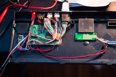
[b10nik] purchased a new Filco Ninja Majestouch-2 keyboard just for this project. Although it may make some people cringe, the keyboard was immediately taken apart in order to find an open cavity for the Raspberry Pi. Luckily there was space available towards the left rear of the keyboard case.

RaspPi2 Keyboard inside
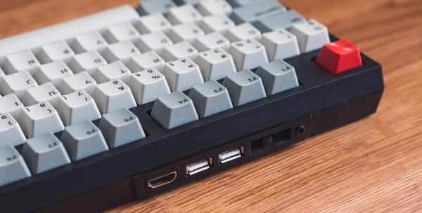
If you are familiar with the Raspberry Pi 2 Model B, you know that all of the connections are not on the same side of the board. The USB, audio, HDMI and Ethernet jacks were removed from the PCB. The Ethernet port is not needed since this hack uses WiFi, but those those other ports were extended and terminated in a custom 3D printed I/O panel . The stock keyboard case had to be cut to fit the new panel which results in a very clean finished look.

There’s one more trick up this keyboard’s sleeve, it can be used with the internal Raspberry Pi or be used as a standard keyboard. This is done by way of a FSUSB30MUX USB switch IC that completely disconnects the Raspberry Pi from the keyboard’s USB output.

For another RaspPi/Keyboard solution, check out this concept from a few years ago using a Cherry G80-3000 mechanical keyboard.


Swapping Dev Board Crystals To Suit Your Needs

Microcontroller Dev Boards have the main hardware choices already made for you so you can jump right into the prototyping by adding peripherals and writing code. Some of the time they have everything you need, other times you can find your own workarounds, but did you ever try just swapping out components to suit? [Andy Brown] documented his process of transplanting the clock crystal on an STM32F4 Discovery board.

Even if you don’t need to do this for yourself, the rework process he documented in the clip after the break is fun to watch. He starts by cleaning the through-hole joints of the crystal oscillator with isopropyl alcohol and then applies some flux paste to each. From there the rest is all hot air. The crystal nearly falls out due to gravity but at the end he needs to pluck it out with his fingers. We’re happy to see others using this “method” as we always feel like it’s a kludge when we do it. Next he grabs the load caps with a pair of tweezers after the briefest of time under the heat.

We’d like to have a little bit of insight on the parts he replaces and we’re hoping there are a few crystal oscillator experts who can leave a comment below. [Andy] calculates a pair of 30pf load caps for this crystal. We understand the math but he mentions a common value for board and uC input capacitance:

assuming the commonly quoted CP + CI = 6pF

So we asked and [Andy] was kind enough to share his background on the topic:

It’s a general “rule of thumb” for FR4 that the stray capacitance due to the traces on the board and the input (lead) capacitance of the the MCU is in in the range of 4-8pF. I’m used to quoting the two separately (CP,CI) but if you look around you’ll see that most people will combine the two and call it just “CP” and quote a value somewhere between 4 and 8pF. It’s all very “finger in the air” and for general purpose MCU clocks you can get away picking the mid-value and be done with it.

That leaves just one other question; the original discovery board had an in-line resistor on one of the crystal traces which he replaces with a zero ohm jumper. Is it common to include a resistor and what is the purpose for it?

Continue reading “Swapping Dev Board Crystals To Suit Your Needs”

DIY Bearing Puller

DIY Car Wheel Bearing Puller

Cars are the greatest. They get you to where you need to go… most of the time. They can also let you down at the worst moment if a critical part fails.  Wheel bearings get a lot of use while we drive and [Dmitriy] found out the hard way how quickly they can fail. Instead of getting cranky about it, he set out to change the damaged bearing himself. In the process he made a pretty neat DIY bearing puller.

Some wheel bearings, on the front of a 2WD truck for example, are only held on by one large nut and easily slide off the spindle. This was not the case for the rear of [Dmitriy’s] AWD Subaru. The rear bearings are press-fit into a bearing housing. These are hard to remove because Outer Diameter of the bearing is actually just slightly larger than the Inner Diameter of the bearing housing. This method of retaining parts together is called an ‘interference fit‘.

BearingPuller2

[Dmitriy’s] gadget uses one of Hackaday’s favorite simple machines, the screw, to slowly force the bearing out of its housing. It works by inserting a threaded rod through the bearing and bearing housing. Each side has a large washer and nut installed as well as a PVC pipe spacer providing support for the threaded rod. As the opposing nuts are tightened, one washer presses against the bearing and the bearing slowly slides out of the housing. Installation of the new bearing is the same except the tool is reversed to press the bushing into the housing.

Continue reading “DIY Car Wheel Bearing Puller”

Your Marble Machine Doesn’t Need To Change The World

It’s easy to get sucked into the increasing the complexity when sometimes the craftsmanship can be what makes the project. [Alex Weber] proves the point with his minimalist marble machine. There are no death-defying twists and turns, no convoluted path forks or overly-complex lifting mechanisms. This is about a clean and simple design that looks amazing whether running or stationary.

For the uninitiated, marble machines route marbles (or quite often steel ball bearings) through a set of paths usually guided by gravity for the delight of onlookers. Traditionally, making them complicated is the point. Take this offering which highlights years worth of marble machine builds all exercising different concepts. Sometimes they occupy entire rooms. We’ve seen them make a clock tick. And who can forget marble-based flip-flops that combine to form things like binary adders?

Have we scared you off from building these yourself yet? No, that’s the entire point of this one… it can be excruciatingly simple, while elegantly crafted. Check out the video demo below to see how one oval, one battery, and one motor have no problem bringing a smile to your face.

Continue reading “Your Marble Machine Doesn’t Need To Change The World”

Active “Dart-Sensing” Makes Your Nerf Gun Smarter

When choosing weapons to defend yourself in the next zombie apocalypse, dart jamming whilst firing your Nerf Gun can be a deal-breaker. This clogging is an issue with many “semi-automatic” Nerf Guns. When our trigger-happy fingertips attempt to shoot a dart that hasn’t finished loading into the firing chamber, the halfway-loaded dart folds onto itself and jams the chamber from firing any more darts. The solution, as intended by Nerf, would be to open the chamber lid and manually clear the pathway. The solution, according to [Technician Gimmick], however, is active sensing, and the resulting “smart” dart gun is the TR-27 GRYPHON.

To prevent jamming from occurring altogether, [Technician Gimmick] added a trigger-disable until the dart has fully loaded into the firing chamber. An IR LED, harvested from a mouse scroll wheel, returns an analog value to the microcontroller’s analog-to-digital converter, allowing it to determine whether or not a dart is ready for firing. The implementation is simple, but the results are fantastic. No longer will any gun fire a dart until it has completely entered the chamber.

The TR-27 GRYPHON isn’t just a Nerf Gun that enables “smart” dart sensing. [Technician Gimmick] folded a number of other features into the Nerf Gun that makes it a charmer on the shelf. First, a hall-sensor array identifies the current cartridge loaded into the Nerf Gun and it’s carrying capacity. To display this value and decrement appropriately, [Technician Gimmick] added a dual-seven segment display, a trick we’ve seen before. Finally, a whopping 3S LiPo battery replaces the original alkaline batteries, and the voltage-reducing diodes have been cropped, enabling a full 12.6 Volt delivery to the motors at full charge.

We’re glad to see such a simple trick go such a long way as to almost entirely eliminate Nerf dart jams. For all those braving the Humans-Versus-Zombies frontier this season, may this clever trick keep you alive for just a bit longer.

Continue reading “Active “Dart-Sensing” Makes Your Nerf Gun Smarter”

Portable 120V To 240V Converter; Or How To Fast Charge At Your In-Law’s House

[Nick Sayer] falls into the “would rather build it than buy it” category. This particular project is a clone of a fast electric vehicle charger. There are commercially available versions sold under the Quick 220 brand name. The idea is that for fast charging, some electric vehicles call for a 240V outlet and Americans without electric cars often don’t have one. If they do it’s for an appliance like a stove or clothes dryer and probably not found in the garage.

The device uses two hot and one ground to supply the 240V output which is, in some business where there is three phase power this will be closer to 208V but should still work. Obviously you shouldn’t be doing this unless you know exactly how it works, and we applaud [Nick] for airing these hazards while at the same time supplying the knowledge behind the concerns.

Two inputs for the beefy converter are supplied from outlets not just on separate circuits, but on two circuits whose hot lines are 180 degrees out of phase. That means identifying where there are two plugs, not protected by GFCI outlets or breakers, which are on two separate hot lines of split phase power. To protect the user, [Nick] designed in a set of relays which kill the circuit when one of the two supplies is unplugged. A system that didn’t have these protections would have mains voltage on the prongs of the disconnected plug.

We’ve seen very few car charging hacks. If you know of one, or have been working on your own, let us know!

MRRF: (not Quite) Chocolate Clock

[Jason] is a woodworker. At least, he was until he saw his first 3D printer. While he may still work in wood, he particularly likes adapting scroll saw patterns for 3D printing. His clock started as a woodworking pattern for use on a scroll saw. To adapt it for 3D printing, [Jason] scanned the plotter-sized pattern pieces into Inkscape, where he was able to do things like add bevels before sending the pieces to OpenSCAD.

tall chococlock
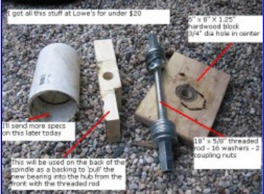
As you might imagine, a great deal of work went into this build, beginning with the scanning. [Jason] starting scanning last October and finished in January. Printing started January 9th, and he told me the final pieces were printed early this morning. We know you want all the details, so here goes: this build took just over six rolls of PLA at 20% infill. It’s 48″ tall and about 24″ wide. It was printed on what [Jason] referred to as his “very modified” Replicator 2. He glued the pieces together with Testor’s, and that took about 30 hours. All through the project, he kept meticulous notes in a spreadsheet of print times and filament used.

We were honored to be among the first to see [Jason]’s incredible clock build at this year’s Midwest RepRap Festival. He would like to take it on tour this year to the nearby Maker Faires. If he can figure out how transport it safely, he’d like to show it at World Maker Faire in NYC.