[Bogdan] makes a good point. When you use a dev board you get programming, debugging, power sourcing, and usually a UART. When you go to the trouble of hooking up a programmer why don’t you get the same thing? Astutely, he points out that all you usually get with programmers is programming. So he set out to add features to the hardware he uses to program XMEGA.
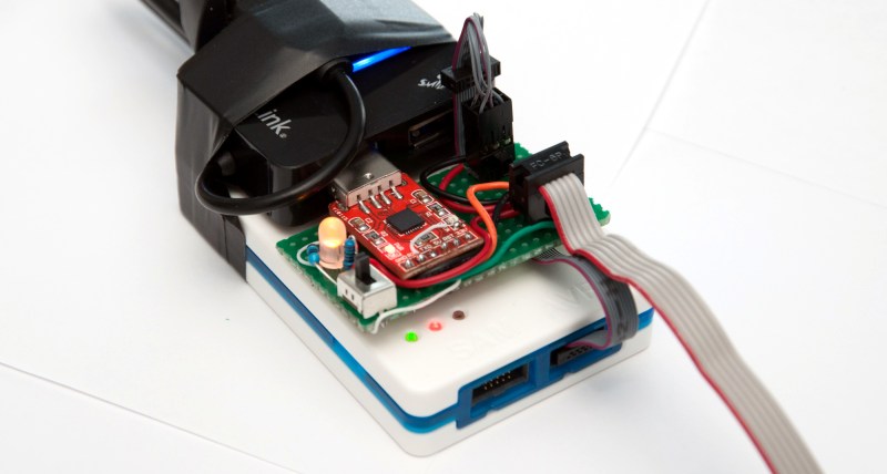
The first part of the trick hinges on his use of PDI programming. This is slightly different from ISP programming. Both use a six-pin connector cable but with PDI two of these pins are unused. He took this opportunity to reroute the chip’s TX and RX pins through the cable, which now gives him an avenue to use a UART-to-USB adapter without adding any cables to his target board. Rather than add a second USB cable he rolled a USB hub into the mix. An LM1117 regulates the 5V USB rail down to 3.3V as a source for the target board.
The programmer being used is an Atmel ICE. As you might imagine he didn’t want to make permanent alterations to it. His modifications are all handled externally, with one IDC cable connecting the programmer to his added circuitry and another headed off to the target board. For now he’s jumpering RX/TX to the programming header but plans to route the signals on future PCBs.


This is nice.
I also has some way-over-engineered programmer project. Let me share you the details. Would anyone be interested in one?
Galvanically isolated ISP programmer with adjustable power supply and high precision current measurement tool.
The idea is to monitor the system without putting an extra power supply and multimeter (uCurrent etc.) on it. Just connect one cable and thats it.
For the usage, you can simulate the battery degratation over time and see the effect of it on the DUT by programmatically lower the supply voltage with a such system.
I am thinking about measuring the current as well, exactly for what you are saying. But i did not do any search on what it would mean to make a current meter with something like 0.5A full scale, 1uA resolution and max 0.1…0.2V burden.
As for the optical isolation… i would probably go for isolating the USB, even though you can only do it easy with 12Mbps rate.
maybe a uCurrent for current measurements? https://eevblog.myshopify.com/
I am very aware of Dave’s design, the opamp he choose is probably one of the best available, but it is not very suited for me, though I will end up making something similar, i will need to make a compromise somewhere else. On his design, when using the scale with 10mohm shunt you will get 200uA error due to the opamp offset, but drop only 10mV at 1A. When using the 10ohm you could read with 0.2uA error due to offset, but you are limited to only a few mAs of load. I might go for something in the middle, like a 0.1ohm shunt.
You can use brute force and use a very high res ADC with a small value sampling resistor.
e.g. TI’s ADS1231 24-bit ADC $6.75 QTY 1 has a full scale of +/-20mV (with internal 128X low noise amplifier). Something like that should get you high resolution, extremely low drop current measurement using a small uC.
Don’t forget about the possibility of USB/IP as an alternative way of isolating the USB. There are sub $20 routers or “3G” routers with built-in Li-ion battery that can power the USB port. You can do a bit better than 12Mbps with either wireless or Ethernet connection.
http://usbip.sourceforge.net/ Their (signed X86/x64) Windows driver is a bit dated, but seems to work well enough.
USBIP can be installed on OpenWRT or Tomator routers as optware. You do want to get a router with 8MB of FLASH for that.
Already tried that about 6 months ago. Did not work with programmer….only common devices like HDD, flash etc. Also, tends to blue screen on windows if you disconnect without removing.
this is ugly. i don’t understand why he integrate the serial in the PDI cable. this doesnt make sense. it require an modification on every board. the serial separate to the PDI with integratet Source is, as i think, the better solution.
I am making my own boards for projects, so why not include the serial there?
if you think this is ugly you should see some of the professional setups used in medium quantity production labs
i have seen 6+ programmers taped together and 6+ perf boards wired all over the shop with a programing jig made of hardware store dwar sliders and programming edge connectors manually wired up with stripped cat5
the point is that it works and is cheap and speeds things up … one of my bosses has a poster of a bodged together calibration system with the tag line “if it looks stupid but it works, its not stupid”
can you take a picture of that poster sometime?
Serously, where can I buy a poster like that?
A Bing search returned ninjanoveltysigns.com but I couldn’t view the page, probably NSFW….
It works and its not competing on a beauty contest
Well, i did have a beauty related dilemma: the USB hub is black while the programmer is white, so should I choose white or black tape to hold the two together?
To be fair i did think of taking out the boards from the programmer and hub and stuffing everything in one box, but it was too much work for no real gain.
Gray Du[ck,ct] tape, it provides a grayscale (of 1) transistion between the black and white.
i dont really see the trouble of hooking up one extra 3 pin cable for UART … makes routing easier and user programming easier …. i have done something similar with an ISP and uart on a 8 pin connector but this was a niche application that required SWD programming and serial com for calibration on a per product basis and the calibration software did not allow us to modify it to just use SWD
granted i mainly use JTAG or SWD these days and do com threw that … i dont know much about ISP but there must be some way to route serial com threw it
something similar with SWD and UART**
I have indeed done it like that for years. But once you start needing some sensor nodes, constantly switching boards, you would appreciate connecting just one cable instead of 3.
Routing is definitely not an issue with the xmegas i am using, the 2 pins next to the programming ones are RX/TX.
well nothing wrong with it if you have a niche purpose
ARM semihosting is a wonderful thing even if it’s slow.
Yes, definitely.
The Freescale K22 chip I used in my HaD project has an interesting pin assignment as they share pins among the different interfaces: SWD/JTAG/Serial/SPI. Share pins: TCK/SWC/SPI Clk, TDO/SDWO/TxD/SPI DO, TDI/RxD/SPI DI
I can either use (SWD + Serial) or (SWD with SWDO for trace/semihosting), JTAG or SPI Flashing in a my 8-pin header. I don’t use their SPI FLASH emulation, but I can see that useful for production. I reuse that /CS as a GPIO during initial debugging.
With those cheap Chinese “Dupont” socket wires, it is easy to mix and match the connections. No messy tapes required.
I have an TI MSP-FET Flash Emulation Tool (a Programmer/Debugger for MSP430s) sitting right here on my desk which does exactly the same thing.
For those complaining about having to modify each board to work with this solution: You could have this DIY programmer/serial combination device with a pinheader, and two kinds of cables to connect it. One that gives you PDI-only and one that has PDI and serial.
For my projects with the nRF24LE1 I created a small 5×5 board with a connector for the nRF module (2mm pitch), translated to the more common 2.54mm pitch and also made sure to put an 2×4 pin connector for a programming cable, this cable provides power, serial and programming (spi in this case) and this gets wired to another similar board that is hooked to an Arduino that I use as a programmer.
It’s a very useful setup as I can switch whole boards to program or just the nRF module as I please and the board also provides a prototype interface or a basic project connection to modules.
Link to the board: https://github.com/baruch/nrf24LE1_programming_board