[Brian B] found a handful of servos at his local hackerspace, and like any good hacker worth his weight in 1N4001’s, he decided to improve upon their design. Most servos are configured to spin only so far – usually 180 degrees in either direction. [Brian B’s] hack makes them spin 360 degrees in continuous rotation (Internet Archive).
He starts off by removing the top most gear and making a small modification with a razor. Then he adds a little super glue to the potentiometer, and puts the thing back together again. A few lines of code and an Arduino confirms that the hack performs flawlessly.
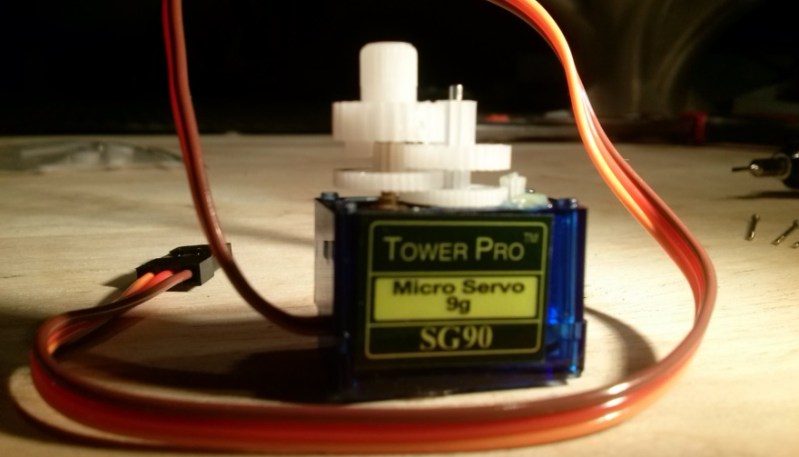
We’ve seen ways to modify other types of servos for 360 rotation. There’s a lot of servos out there, and every little bit of information helps. Be sure to check your parts bin for any Tower Pro SG90 9g servos and bookmark this article. It might come in handy on a rainy day.


Congratulations. You have now turned a servo into an over complicated geared motor …
A ridiculously cheap geared motor with easy-peasy digital interface and built-in h-bridge.
On the other hand, this definitely falls into the reported-before category, but hey it’s a handy hack, I’m sure some reader will have missed it in the past and be able to use it in the future,
did the same thing last year, http://nesit.org/modding-a-tower-pro-micro-servo-to-rotate-360-degrees/ a bunch of people already had tutorials on it
+1
One of the key points to any servo (continuous rotation or otherwise) is the negative feedback. Removing the potentiometer kills the negative feedback, but hey I guess it works as a cheap fix if you are using it to move VERY light weight loads
These types of hacks are very common in robot worlds with Antweight fighting robots (well beginner ones) as plug 2 of these modded servos into an Rx and you have a drive train ready fir some wheers, including speed control and a round horn to stick a wheel on to.
An over complicated geared motor but with variable speed control. I’ve hacked a few servos like this – the 9g ones are particularly fiddly – and being able to change the speed by simply setting a new “rotation angle” is really useful in a lot of projects.
If you run the arduino code while tweaking the pot, won’t you be able to find the ‘stop’ spot and avoid the creep?
I’ve done this exact mod on this exact type of servo. I’ve also done the resistor version for this servo. I can confirm that finding the “zero” value that stops all rotation is notoriously difficult, and this value can creep in either direction. It’s ok for applications that have feedback, such as self-balancing two wheeled robots, but otherwise modding this servo is a waste of time.
Better solution si replace potenciometer with trimer or two rezistors.
If you want to use it as 360deg servo, you have to monitor different axis which is´geared down to 1:2.
https://youtu.be/qtj2qAK9fes
+1 for the suggestion of using 2 resistors. I did the same on Naro Micro Servos for a miniature version of Parallax’s Stingray robot. See post #23 for details and the pictures on later posts on this thread: http://forums.parallax.com/showthread.php/146321
i’ve tried the 2 resistor method in the past with limited success
no matter what combination of resistor values i used, it was impossible to match the neutral position of the pot enough so that it would not jitter clockwise or counter clockwise
i dont know if the pot was insane sensitive or if the resistance of the solder was fucking things up, but i would recommend OP’s hack over the 2 resistor method any day
You can tune the resistors slightly by filing at the side of the package, then put a drop of epoxy to cover the hole you made to prevent corrosion.
You essentially guess which one of the resistors is a bit low and then file it until you find the center.
Or get a proper precision multi-turn potentiometer and replace the original with that.
You can also hack in a crude encoder like I did 10 years (yuck) ago
http://sensi.org/~svo/shaft_encoder/
And if you need even more resolution than your solution you can use the optical fork sensor + wheel of an old mechanical computer mouse. To be honest it was a challenge to get all of the mechanics in this small housing, however, the result was great and extremely cheap.
Sure, that would be even better. I’m actually quite interested in hacked up encoders. The one I made just yesterday uses a mouse wheel sensor from a logitech mouse. It requires 1 line/mm encoder wheel, which is easily printable on any printer and if you can afford a disk with a diameter of 57mm it has 180 lines, which gives 720 counts/revolution at x4, which is not too bad unless you’re making a delta robot or a telescope mount.
Now if someone could give a piece of advice on how to make, a 180 lpi encoder disk for a more serious encoder, that would be nice. 180 lpi does not sound like much, but all printers I have tried so far, all claim 1200dpi, go tits up and print pixelated moire patterns.
Yes, I know I can buy a complete encoder for not too much. That’s besides the point.
Maybe the printer driver is trying to scale the design to the paper with an algorithm that isn’t suited?
I tried several printers with various settings, the result is always more or less the same every time. Maybe the proper way is to use a HP printer and generate the PCL directly, but I’m reluctant to try that. One of the wilder ideas that I have is to print a large scale wheel and photograph it on a 9×12 photographic plate. Getting the scale right would be quite difficult with this method.
You can salvage a rotary encoder from any inkjet platen (they even have a decent motor attached). The print head strip usually has a linear encoder. The printhead encoders are usually 150 lpi, so 600 DPI resolution with quadrature encoding.
In my experience they mostly use steppers. I only found one with a linear 180 lpi encoder. I guess different regions get different models and brands, but here I just don’t find many encoders.
If you need higher resolution, you might be able to do with old fashion analog photo reduction process. Years ago you could get contact films printed in a professional graphics print shop. Not sure if those are still around in the digital age.
I wonder if the capacitive position sensor like the one used by Elm-chan’s galvanometer for a laser projector would be useful. It is a simple circuit and easy enough to be make with PCB and the output is a linear analog DC signal.
http://elm-chan.org/works/vlp/report_e.html
A nice idea, an option I haven’t yet tried. Though I want something that’s also good for continuous rotation, otherwise I’d just use a potentiometer.
I’ve been playing around with the IR mouse sensors (search for “optical flow” in eBay). The cheap ones have 600 or 900 DPI resolutions, but you can get (on eBay) ones made for gaming mice that have insane resolutions – up to 8K DPI or some such.
If you’re interested, I’ve got a driver and dev software that shows the registers in real time for debugging. Contact me on .IO if you want it.
Thanks! I already have ADNS-9800 and I tried the ins and outs of it but I’ve found out that although its local resolution is indeed very high (up to 8000 counts per inch), it always slips very quickly and pretty severely. I even tried achieving perfect focus and providing it with a good surface, implemented a realtime camera view for that. But it slips regardless. An interesting alternative would be to use its camera to read some kind of code for an absolute encoder, it has a theoretical maximum of about 60fps in such mode — although thanks to retarded SPI implementation in the sensor you can’t use DMA to transfer the frames, at least not on a simple micro like stm32f103. Anyway, the real problem is that with the supplied lens the focused surface area is only a tiny bit larger than 1 square millimeter and printing such a tiny code and then aligning it perfectly is just too hard for something homemade. You can take a look at my video capture experiment here
http://www.youtube.com/watch?v=37Fg5_77J24
I think in a project of its own it decoding could be achievable if the lens is replaced with something that focuses on a larger surface area and/or has active autofocus on a voicecoil, like a CD-ROM lens. I’ve found a suitable lens, but making a tiny adjustable mount for it is not very easy. It also “helps” that in this sensor the camera is located at an angle to the surface.
My current code for ADNS-9800 if anyone’s interested is here. Be warned, it’s not pretty: https://github.com/svofski/bldc/blob/master/stm32src/blink-cmsis/src/adns-9800.c
The camera mode is a complete hack that just enters an eternal loop dumping frame data to the serial.
Now this is how you hack a continuous rotation servo!
I did a similar hack recently http://inventorartist.com/continuous-rotation-servo-hack/
Is very handy. You can have a motor running with proportional speed in both directions without an h-bridge. Plus there’s already a gear box.
Then there’s the issue of affixing stuff to the shaft. One angle is to attach the servo arm http://inventorartist.com/rolly-bot/.
That answers my suggestion of running the code while tweaking the pot… :)
Yeah, it helps you find the center better. I leave it running even waiting for the glue to dry (in cases where I glue the pot)…
Another thing is in the software I use to drive the servos I have a “zero variable” where I can adjust zero… (actually 90 in the arduino library I was using)…
Or you can buy a full rotation servo for RC sailing ships. That are even available at chinese discount sites. But hey… Who here would want to do anything smart without any pseudo bragging right when you can instead use the wrong tool and make it fit with a potato and a sledgehammer.
But when all you have is a potato, a sledgehammer and maybe a tight deadline…
Wow. This hack is at least 20 years old. Great job everyone!
What would it take to modify a servo to open up the range but still act like a normal servo? I’d like to have a servo go +/- 180 (or greater if possible) but still be able to go back to a home position.
It’s possible but with a bit of work. You need an incremental encoder (e.g. quadrature encoder) to count current position and an index mark to find the rest position.
Or you could use a different gearing ratio on the potentiometer, but as mentioned above, you would lose some resolution.
or a multi turn pot?
They make these for model sailing ships. Not continuous, but multiple rotations from full left to full right.
Ahemmmm,
Since a 1N4001 weighs about .3 grams and an average person weighs about 175 lbs that would be the weight equivalent of about 265000 diodes.
Checking top tier Digikey quantity discou.nts puts a hacker’s value at around $8200.
Just sayin’ … seems a little harsh.
My mom says im priceless
His hack? Sorry most of us have been doing this for over a decade or more. and RC guys have done it for decades before that.
This is a very common modification.
1977 if I recall correctly on a 1st generation World Engines proportional radio control
Yep, it has been around quite a while, but the kids here may have not seen it.
Yup, over a decade. The trick has been used in the commercial “Boe-bot” robot kit from Parallax since 1998. The manual had a good description of how to disassemble and modify and trim the servos, you had to do that yourself at that time. The kit now has continuous rotation servos instead.