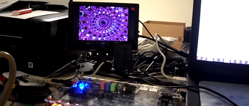
This FPGA based build creates an interesting display which reacts to music. [Wancheng’s] Dancing Mandelbrot Set uses an FPGA and some math to generate a controllable fractal display.
The build produces a Mandelbrot Set with colours that are modified by an audio input. The Terasic DE2-115 development board, which hosts a Cyclone IV FPGA, provides all the IO and processing. On the input side, UART or an IR remote can be used to zoom in and out on the display. An audio input maps to the color control, and a VGA output allows for the result to be displayed in real time.
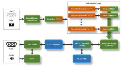 On the FPGA, a custom calculation engine, running at up to 150 MHz, does the math to generate the fractal. A Fast Fourier transform decomposes the audio input into frequencies, which are used to control the colors of the output image.
This build is best explained by watching, so check out the video after the break.


Wouldn’t ‘dancing’ involve.. movement? This is just flashing fill areas of the same set to the music, I honestly expected it to morph because of the sound input. This is simply sound-reactive otherwise.
Dear Nova,
Thanks for your suggestions. The fact is that with 1024×768 resolution, it would be very difficult to realize real-time ZOOM or PAN due to the limitation of hardware multipliers and the single-port SRAM. With dual-port RAM composed of M9K blocks and more multipliers, it maybe possible to implement real-time ZOOM or PAN based on FFT audio analysis. In this project, “dance” just mean color. :(
I will definitely try realtime ZOOM or PAN with advanced FPGAs.
Perhaps a Julia set instead, or controlling bloom to give the impression of pulsing zoom?
Linus Akesson does something similar in his Parallelogram demo: https://youtu.be/h42neZVvoMY?t=232
Yeah, that’s what my initial idea. However, I still want to explore the calculation power of FPGA, so both the iteration limit and resolution are raised. Furthermore, I also want the mandelbrot to be more “colorful”. I guess I cannot own all of them with limited hardware. :(
Anyway, I will need to re-design the whole stuff – either beautiful color with higher resolution or real-time ZOOM/PAN with lower resolution (iteration).
Yeah, it is just old-school LUT manipulation like back in the demo scene days. I wonder if the FPGA has enough computational power to animate the actual parameter space for a julia set to that the geometry of the data is “dancing” in relation to the FFT of the audio?
Dancing geometry actually means real-time ZOOM and PAN. Also, it is not LUT manipulation – Even though I just use FFT audio to control the color rendering (There still exists many ways to do this).
Single-Port SRAM is used as the display buffer, it is one of the bottlenecks in this design – You need to carefully mediate the Read (VGA Display) process and Write (Calculation Core) process. The maximum clock for SRAM R/W is 120MHz (datasheet). The other bottleneck is the number of hardware multiplier and their performance. More hardware multipliers can be used to compose more calculation cores which makes it possible to finish the calculation within 30ms (real time).
Advanced FPGAs may be able to achieve this by using dual-port RAM composed of LUT and M9Ks. Since dual-port RAM split Read / Write process and it is definitely faster than SRAM.
Awesome project, and I don’t want to sound like a grinch, but there are some calculation errors going on.
If you have a look at 0:04 seconds there are little islands where their shouldn’t be any.
These are present (although smaller and less obvious) at other zoom levels without performing direct comparison.
As everything else looks correct it might just be the “|ai+b| > 2” test that terminates the iteration being a bit off – maybe an tiny window to overflow?
Dear Mike,
You are my idol for your great design posted in Hamster! ^_^
That’s a Great catch! :) I will double check that!
I would like to enhance the resolution using HDMI TX board in the future. And my original idea for this project is to let the mandelbrot set dynamically ZOOM in/out or PAN in realtime based on FFT audio analysis. It would be very very difficult @ 1024×768. I guess with this calculation architecture can zoom in / out or PAN in realtime with the resolution 640×480. Would have a try too.
Say the upper limit for the inner loop is 256 iterations, and the target frame rate is 720p60, ( 55,296,000 pixels per second).
A well designed and highly tuned engine can process the inner loop (a <= a^2+c) at around 225MHz, allowing each engine to completely process 880 thousand pixels per second, you will need at least 63 pixel engines to calculate the entire screen in real-time, allowing real time pan and zoom.
On Xilinx (which I am most familiar with) each fractal engine requires 10 DSP blocks (the limiting resource), so will need an FPGA with 63×10 = 630 DSP blocks. The largest low-end Xilinx FPGA is the Artix-7 XC7A200T (at just under US$300 on Digi Key), which has 740 DSP blocks, just enough to do real-time Mandelbrot 720p.
Sadly I've only got a XC7A35T, about 1/6th of what is needed :(
I use 1024 iterations in current design which is definitely bad for Real-Time calculation. Assume we use 256 iterations, as you said, we will need at least 63 calculation cores running at 225MHz to achieve Real-Time calculation. However, 720p60 display require large display buffer. I am sure that most SRAMs cannot achieve 150MHz R/W performance. What’s more, SRAM is single-port (you will need to carefully split the read and write process).
Indeed, Real-Time calculation is very important, but the display buffer is also essential. Dual-Port RAM is the best choice, but it will occupies so many M9Ks and LUTs with 720p resolution. It is definitely a disaster.
I used EP4CE115 in this project, currently, there are 16 calculation cores running @ 150MHz, and it already consumed 75% of the total hardware multipliers….
The SRAM and a frame buffer is only needed because of the limits in the smaller FPGA’s compute resources.
If you can generate pixels in real time you don’t need a frame buffer – the only storage you only need to have the pixels that are running through pipeline.
An easy implementation would be to have 86 calculation stages, running three times faster than the display pixel clock. Two times out of three cycles you feed the output of the final stage into the input of the engine, the third cycle you send in a new pixel. On the output of engine 84, you pull out every third pixel. Due to the 3 and 86 being relative primes ,when it is pulled from the pipeline it has cycled through 86+86+84 = 256 calculation stages (if you get the phasing correct)
This value can then be sent it through to the display, without a frame buffer being needed.
Yeah, you are definitely right. Buffer can be eliminated. I guess the first thing I can try is to lower down the number of iterations to see whether it can achieve Real-Time.
For 1024×768 resolution, the pixel clock would be 65MHz, which means I will need to clock the calculation core @ 190 MHz. I will definitely need to re-design the calculation engine. But there’s a performance limitation on hardware multipliers. With 9×9 multiplier, the maximum frequency is 340 MHz, while with 18×18, the frequency is 287 MHz. Currently, I pipelined the multiplier into 5-stages which can run @ 150 MHz. I guess I will need to design the multiplier by myself without using Altera’s MegaWizard.
I will try your great suggestions. :)
To make it easier to make it in time for buffer-less computation, would it help to lower the display resolution? 480p @ 25MHz pixel clock is not bad at all.
That is real-time Mandelbrot
http://users.softlab.ntua.gr/~ttsiod/mandelSSE.html
but yes, no fancy FPGA, just your everyday GPU and Cuda
Well you got your pallet swap code decent, 5 points for the CGA.
1:17 “uuuuuummmmm” Either you don’t know you are storing and trying to saving the entire origin equation or can’t define why your processing speed is “taking longer”. -5
1:50 “light blue and dark blue” so how can you prove the frequencies are bound to the upper or lower range when there isn’t any difference between the tearing and the processing rate? -10
2:12 “didn’t calculate that accurately”, listen here. you have 2 team members. BOTH were going to speak and the LADY was going to mention the factors of the aproximations, meaning you even ignored her the first time she mentioned it. -10
2:31 “no large area black stuff”. No what? I’m sorry? Did you say memory limit or memory leak in the code? -5
2:”49 I can tell if you are “gulping” because you are afraid you aren’t explaining it right or that you are making it up. So what scheduling routine are you using? FIFO? CFQ? 16 pipelines huh? So? I mean it’s cool if you said “Yeah, there are some limits because sometimes the GIL is actually recieving and processing data so it has some trouble negotiating the process cycle” but NO, you GULPED. -5
3:24 watching the frames there… So the white doesn’t alternate, the red/pink/white areas are static as well. I’m seeing a real problem here. -5
3:42 – Other team clapped. When they heard you explaining, “16 pipelines?” okay score for 3:24 should be clear. “calling from SRAM”. and just because your are should more then combination of white/cyan/magenta and black. This is not VGA.
4:03 – “which means that, stuff that I didn’t do that I thought about doing, in fact looking at my other team member because I was too lazy myself, could be done to help things.” Hmmm. Hmmm. you mean not saving the last 3 iterations and flushing the sram? could have helped? Wow, that sounds really nice. So maybe a actually using the Garbage Collection function. -50
4:06 – “Even if the resolution is higher”. Where? At the LVDS level? or the Signal Generation layer? ‘VGA’ okay please continue.
“still reuse some data space.” W.T.F.
Okay if you are going for your B.S. in EE I’d give you an A- (9.5). Hey I wrote the exam, ergo you got the final exam right. You got it working.
If you are going for your Grad/Masters Thesis? You get a D- (that is a 4.5 Euro style) you have 2 weeks to redo the work alone.
“Last semesters project” Thank you commenter.
That means the guy is a T.A. waiting to leech the work off any incoming students.
I want someone to zip-tie/duct-tape this man down and rip out his chin hairs one by one. Utterly dishonorable. You open with “we did this last semester and have been having a hard time allocating time to add further refinements. BUT here is our CODE!”
Final grade? Your Kung Fu is sh1t go back to the forest forever.
Thanks for your patience to go through my video, and for some of your suggestions. I know my speaking english is bad.
1:17 “uuuuuummmmm” Either you don’t know you are storing and trying to saving the entire origin equation or can’t define why your processing speed is “taking longer”. -5
—————————————————————————————————————————————————
A: My team member answered this question, and his answer was incomplete. Further zoom doesn’t mean more time, actually, we cannot estimate the time accurately since the number of iterations varies. However, if the whole screen is black, then I can calculate exact cycles – all points are not in Mandelbrot Set. Forgive me, but your comment is hilarious. In FPGA design, there’s no “store / save”, everything is designed in hardware.
1:50 “light blue and dark blue” so how can you prove the frequencies are bound to the upper or lower range when there isn’t any difference between the tearing and the processing rate? -10
—————————————————————————————————————————————————
A: As I described in my report. cFFT output the FFT analysis results sequentially. I bounded the index (seq#) of the FFT result to the index (color entry#) of the color palette. Light blue and dark blue actually stands for the real FFT amplitude of. In other words, if two region are colored with light blue and dark blue, it means that the number of iteration for these two regions are different.
2:12 “didn’t calculate that accurately”, listen here. you have 2 team members. BOTH were going to speak and the LADY was going to mention the factors of the aproximations, meaning you even ignored her the first time she mentioned it. -10
—————————————————————————————————————————————————
A: That LADY actually do software simulation using JAVA trying to figure out how to map the FFT results better to color space. Accurately speaking, there is no approximation in the mapping process (FFT=>color space). Because the amplitude of FFT itself is used as the color RGB value.
2:31 “no large area black stuff”. No what? I’m sorry? Did you say memory limit or memory leak in the code? -5
—————————————————————————————————————————————————
A: Black area means that the number of iterations exceeds the defined value (1024). If so, the point is not in Mandelbrot Set. This comment means that you don’t know Mandelbrot Set display, or don’t know hardware implementation of MandelBrot Set Display. There’s no such memory limit or memory leak in hardware design – unless you are using NIOS-II and you are a bad programmer.
2:”49 I can tell if you are “gulping” because you are afraid you aren’t explaining it right or that you are making it up. So what scheduling routine are you using? FIFO? CFQ? 16 pipelines huh? So? I mean it’s cool if you said “Yeah, there are some limits because sometimes the GIL is actually recieving and processing data so it has some trouble negotiating the process cycle” but NO, you GULPED. -5
—————————————————————————————————————————————————
A: Yeah, I must admit that I didn’t explain this part well. I designed two different kinds of FIFO: TASK FIFO is responsible to distribute the “Task” (mapping results from real display coordinates to complex plane coordinates) to 16 parallel calculation cores. When all the pipelined cores finished calculation, we have 16 results need to be stored into single-port SRAM. So I designed 16 “Result” FIFOs for each calculation core, then every calculation core doesn’t need to wait until all 16 results are written into SRAM.
3:24 watching the frames there… So the white doesn’t alternate, the red/pink/white areas are static as well. I’m seeing a real problem here. -5
—————————————————————————————————————————————————
A: How to map the FFT result to color space is very important in this project. A good way to visualize the FFT is to keep part of the color static while changing the color of other parts. Specifically, the white doesn’t alternate because the frequency point index doesn’t reach the color index (stands for iteration #). I can change the hardware design to alternate other colors or all colors, but it would be difficult to visualize the FFT audio analysis results.
3:42 – Other team clapped. When they heard you explaining, “16 pipelines?” okay score for 3:24 should be clear. “calling from SRAM”. and just because your are should more then combination of white/cyan/magenta and black. This is not VGA.
—————————————————————————————————————————————————
A: For your information, VGA can go higher resolution. http://www.tinyvga.com/vga-timing Another team member tried hard to implement HDMI display but failed. From 3:42 I tried to explain that with my current design, I can still use VGA to achieve higher resolution with limited hardware resource. And again, for your information, 16 pipelined calculation cores already consumes 75% of hardware multipliers. That’s the hardware limitation.
4:03 – “which means that, stuff that I didn’t do that I thought about doing, in fact looking at my other team member because I was too lazy myself, could be done to help things.” Hmmm. Hmmm. you mean not saving the last 3 iterations and flushing the sram? could have helped? Wow, that sounds really nice. So maybe a actually using the Garbage Collection function. -50
—————————————————————————————————————————————————
A: Sorry for my bad speaking english. In fact, I was trying to explain that I also implemented “Read-Modify-Write” SRAM controller. The SRAM R/W width is 16-bits, so I can take advantage of the wide bit-width and downsample the results to 4 bits, in this way, each 16-bit cell in SRAM can store 4 results. In other words, I can store more display points (if resolution goes higher) into SRAM. But the R-M-W SRAM controller is much slower since every time you will need to read out the result firstly, modify part of it and finally write it.
Also, for your information, I nearly implemented the whole project all by myself. And it took me the whole spring holiday.
4:06 – “Even if the resolution is higher”. Where? At the LVDS level? or the Signal Generation layer? ‘VGA’ okay please continue.
“still reuse some data space.” W.T.F.
—————————————————————————————————————————————————
A: As I explained above, there’s no HDMI, only VGA. With limited SRAM capacity, if the resolution goes high, you definitely needs to reuse the SRAM (R-M-W).
“Last semesters project” Thank you commenter.
—————————————————————————————————————————————————
A: The project of my last semester is a AVR wave player. In fact, I can directly plug the audio line into PC speaker output to show this work.
I want someone to zip-tie/duct-tape this man down and rip out his chin hairs one by one. Utterly dishonorable. You open with “we did this last semester and have been having a hard time allocating time to add further refinements. BUT here is our CODE!”
—————————————————————————————————————————————————
A: For your information, most of your comments above shows you don’t understand Mandelbrot Set and you know nearly nothing about hardware design. And again, for your information, I designed the AVR wave player project (last semester) all by myself. http://hackaday.com/2014/12/25/8-bit-chip-rocks-16-bit-44-1khz-tunes/
Anyway, thanks for your patience to go through my project video.
Okay if you are going for your B.S. in EE I’d give you an A- (9.5). Hey I wrote the exam, ergo you got the final exam right. You got it working.
If you are going for your Grad/Masters Thesis? You get a D- (that is a 4.5 Euro style) you have 2 weeks to redo the work alone.
—————————————————————————————————————————————————
Seems I forgot to respond to this comment.
These two projects shown in the video are actually course projects (ECE4760 and ECE5760). And again, you are not qualified to be my teacher for your ignorance in hardware design.
For Big_Ups:
This student’s project may not as good as yours, but if you can, make a better project to teach him. Your ridiculous comments expose your poor engineering background and uneducated vulgarity.
For Wancheng Zhou:
Ignore his comments, but your speaking english definitely needs improvement. :)
As Mike FIeld said, you can try to make real-time zoom, it would be more interesting if you make mandelbrot zoom to different degrees based on fft analysis.
Thanks, I will definitely try this approach.
[ethan] – “expose your poor engineering background and uneducated vulgarity”
You are so entitled to think that way. I have zero qualm with that. Vulgarity in itself is more about a direct, straightforward and undiluted combined with a emotional tone pertaining to that message/statement/viewpoint.
I suppose a fundamental aspect of criticism is full self awareness on ones own weakness and ultimately self-reflection of ones being. However you may perceive it I have little or no tolerance for pretentious (or is it ostentatious, I don’t remember) character types. Typically since working with them becomes a bore and breeds toxic environments as never admiting wrongdoing and looking to blame others is not healthy. Inversely protecting ones team and taking the blame for any problems does inspire loyalty and confidence in the people that work with you. That matter aside. *shrug* On a personal level – overall I felt he copy pasted source code and it mashed together.
That said: I am very fond of projects that “show us the source” or walk us through even the most basic steps (wiring diagram?). Of particular interest is chanlenges or difficulties in the project. What routes did one explore before settling on this particular solution?
Good hallmarks of character are using phrases such as “I didn’t have a chance to attempt a different option”, “I didn’t have a chance to fully research why I have difficulty in this particular area”, “I don’t remember exactly how we solved this issue but I documented it/wrote it down”. Basically the caveats of ones character.
I guess it really boils down to the fact that one you accomplish something with the help of others and you don’t even awknowledge their contribution.
I suppose the more important words aside from “please” and “thank you” are “I don’t know.”
Now as far as background? It is entirely possible I worked in too many domains? So jack-of-all-trades and master-of-none might be applicable. That said I’m always learning.
I guess the one thing that red flagged the entire thing was not even mentioning avoiding the julia set.
What little I remember is that the Mandelbrot is a Fractal equation therefore it is supposed to have an possible infinite iteration sequence.
Probably running a Sierpinski carpet would have been more simple and demonstrate the full capabilities of the hardware design.
Ha. Who are we kidding I’m completely ignorant in hardware design. Good day.
What is polite in one culture isn’t always obvious from another, but I am pretty sure that rudeness is obvious in most.
I think the achievement that the team has made is awesome. It isn’t just a matter of writing z(n) <= z(n-1)^2 + c and hitting 'compile'.
When I made my first FPGA Mandelbrot viewer it too me ages. – two months ofspare time effort. Writing and debugging DRAM memory controllers, learning how to use DSP blocks, meeting timing, working out how to schedule processing pipelines, and a whole lot of other stuff like working out how to talk to a mouse. On top of that debugging math (or anything!) in an FPGA is a complete pain in the bum, even with years of experience.
I can say that for a student project this is an awesome achievement, and shows that they great potential and have learnt a huge amount building their project.
I was inspired by this project's efforts, I'm now working on a new more advanced design, and given 5 years of FPGA experience I am closer to being able to make full use of the hardware (well, if 100% of DSP blocks churning at 250MHz is considered full use). It's awesome (if I do say so myself) – a 1,560 stage pipeline for each pixel between the VGA generator and the screen, with super smooth scrolling and zooming. The FPGA power usage is 1.6W. Expecting that like that from a student project is a bit silly.
So I can honestly say you guys are truly inspirational!
Thanks, Mike!
I am now trying to re-design the data-path and system architecture. I just found that if I am not going to use buffer, I have to deal with the sequential display (VGA controller always display pixel one-by-one) and nonsequential calculation results ( with parallel calculation module deployed, the results are not generated in sequential – those results with small iterations are generated faster ). How to solve this problem is not that easy. I am trying to figure out a way to deal with it.
Real time fractal viewer that does zoom in real time: http://www.zevendevelopment.com.