If you’re entering something in The Hackaday Prize this year, [Peter Jansen] is a guy you need to watch out for. Last year, he won 4th place with the Open Source Science Tricorder, and this year he’s entering a homebrew MRI machine. Both are incredible examples of what can be built with just enough tools to fit on a workbench, but even these builds don’t cover everything [Peter] has built. A few years ago, [Peter] built a desktop CT scanner. The CT scanner worked, but not very well; the machine takes nine hours to acquire a single slice of a bell pepper. At that rate, any vegetable or fruit would begin to decompose before a full scan could be completed.
This didn’t stop a deluge of emails from radiology professors and biomedical folk from hitting [Peter]’s inbox. There are a lot of people who are waiting for back alley CT scans, but the CT scanner, right now, just isn’t up to the task. The solution is iteration, and in the radiology department of hackaday.io, [Peter] is starting a new project: an improved desktop CT scanner.
The previous version of this CT scanner used a barium check source – the hottest radioisotope source that’s available without a license – and a photodiode detector found in the Radiation Watch to scan small objects. This source is not matched to the detector, there’s surely data buried below the noise floor, but somehow it works.
For this revision of a desktop CT scanner, [Peter] is looking at his options to improve scanning speed. He’s come up with three techniques that should allow him to take faster, higher resolution scans. The first is decreasing the scanning volume: the closer a detector is to the source, the higher the number of counts. The second is multiple detectors, followed up by better detectors than what’s found in the Radiation Watch.
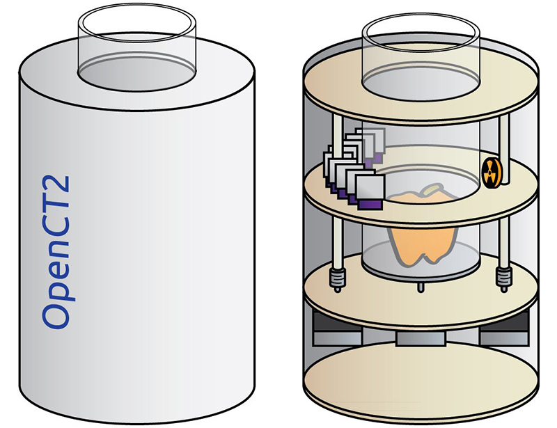
The solution [Peter] came up with still uses the barium check source, but replaces the large photodiode with multiple PIN photodiodes. There will be a dozen or so sensors in the CT scanner, all based on a Maxim app note, and the mechanical design of this CT scanner greatly simplifies the build.
Compared to the Stargate-like confabulation of [Peter]’s first CT scanner, the new one is dead simple, and should be much faster, too. Whether those radiology professors and biomed folk will be heading out to [Dr. Jansen]’s back alley CT scan shop is another question entirely, but it’s still an amazing example of what can be done with a laser cutter and an order from Mouser.


I’ve been following this for awhile. Peter’s insight is to use coded aperture processing to compensate for variations in the magnetic field strength.
A limiting factor in MRI processing is the uniformity of the magnetic field. Proton precession frequency is very sensitive to magnetic field, so any slight variation in the field causes significant decrease (or increase) in reflected RF, which is measured as more (or less) density in the subject where there is none.
Commercial MRI machines minimize this by making the field really big. An MRI is essentially a big Helmholtz coil, and the bigger the coil the more uniform the field is within the coils.
If you know ahead of time the variations in magnetic field strength, you can consider the variations as a coded aperture signal and compensate for the variations.
Okay, coded aperture: assume you have a single sensor, such as a photocell, inside a pinhole camera. By placing checkerboard filter patterns ahead of the sensor, you can get the total amount of light passing through the holes in the checkerboard (the other sections block the light). By using successive patterns you get more and more information about individual pixels.
Coded aperture processing is choosing patterns in the right way to maximize the information you receive during each frame. For example, if early on you discover a large section of the input image is completely white, you can black that section out in subsequent frames and look in more detail at remaining sections. This means that you can deduce NxN pixels in less than N^2 frames using a single sensor.
(And coded aperture processing is much more deep and interesting than this simple example.)
Peter believes that variations in magnetic field intensity can be processed as coded aperture samples, and so he should be able to compensate for the variations and get good images,
If it works it will be a proof of concept and a step-wise improvement in MRI technology.
(Oh, and note: MRI systems do not require liquid helium and/or superconductors. Any magnetic field will work, especially for a proof of concept.)
I never heard of the term before. It reminds me of masking in the plane of the Fourier Transform produced by a simple lens. Gonna have to do some reading!
From industrial x-ray work I have done in the past, today I would experiment with a shielded cooled linear CCD (or a camera chip) looking at a strip of fluorescing screen by means of a mirror or fiber optic bonded light pipe (make your own). Why multiple diodes when you can get a great 4K array for a few bucks? Why not a cooled CCD camera chip, the inner face of an old CRT for a detector screen? OK, maybe this version should be my entry :-)
BTW, it is pretty easy to make an x-ray tube. The old Scientific American book of experiments for the amateur scientist from the 1960’s has instructions for kids.
Hi,
I like your suggestion.
“Ben Krasnow” had a “similar” lowtech version of the setup you described
– x-ray source
– rotating table
– fluorescent screen
– video camera
https://www.youtube.com/user/bkraz333
He took the fluorescent screen from old analog style x-ray exposure sheets, where the screen – being hit by x-rays – would expose a photographic film to light. (you can get those from ebay for ~20-50 €/$ – without breaking your grand parents old tubish TV).
Peter Jansen wanted to design an open source project that any US citizen could build with the proper skills. Because using or building an X-ray tube requires NRC licensing, Peter chose to use a sealed check source that requires no license. This allows nearly anyone in the US to obtain the required source. The down side to this source is of course the lower X-ray flux at the detectors, which requires some clever detection schemes.
Because the diodes he is using can detect the the X-ray photons directly. It is a more efficient use of the limited X-ray source he has.
I was thinking a scintillation detector of appropriate geometry may improve detection rates. He would simply integrate the counts over a unit of time to determine transmitted X-ray intensity. The relatively low photon energies of his source do pose a problem in scintillation detectors though.
I don’t see why this guy is making such a meal out of making a CT scanner. It’s not tremendously difficult to get decent results using a 2D imaging method, e.g. https://www.youtube.com/watch?v=hF3V-GHiJ78
Hi,
the hardware for a CT-scanner is indeed “easy”, rotate the source take shots from different angles and then …
watch the pictures .. but they look different than those from your last doctors visit after you took that nose dive.
What CT-Scanners really do from this data is to calculate the “interior” in reality it only does calculate back the “density” which even isn’t that reality, it calculates back at which region a certain amount of radiation was absorbt to a higher degree than in another region – and this is due to density differences in the tissue.
The wikipedia article sadly is a bit low on theory of calculating those images. But much information is avialiable on the internet mostly from classes tought at universities about applied mathematics.
Also with a working CT you can look inside things without dismantelling them, for example in industry applications CTs are used for example to find pores in the resin – which will lead over time to a short – in mid sized transformers.
These CTs have a very very strong xray source.
http://en.wikipedia.org/wiki/X-ray_computed_tomography
Search on “Image reconstruction from projections” or Amazon for plenty of expensive books. There are plenty of university projects with open source in Python or iPython Notebook and NumPy, etc.
Since the detector amplifier needs low current noise and low voltage noise, this might be a good spot for a composite op-amp circuit. I.e. build an input stage out of a discrete FET/J-FET with a cheap op-amp to provide the bulk of the gain. For example http://www.linear.com/solutions/1206