Putting The Magic Smoke Back Into A Dodgy Spectrum Analyzer

The trouble with fixing electronics is that most devices are just black boxes — literally. Tear it down, look inside, but it usually doesn’t matter — all you see are black epoxy blobs, taunting you with the fact that one or more of them are dead with no external indication of the culprit.

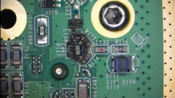
Sometimes, though, you get lucky, as [FeedbackLoop] did with this Rigol spectrum analyzer fix. The instrument powered up and sort of worked, but the noise floor was unacceptably high. Even before opening it up, there was clearly a problem; in general, spectrum analyzers shouldn’t rattle. Upon teardown, it was clear that someone had been inside before and got reassembly wrong, with a loose fastener and some obviously shorted components to show for it. But while the scorched remains of components made a great place to start diagnosis, it doesn’t mean the fix was going to be easy.

Figuring out the values of the nuked components required a little detective work. The blast zone seemed to once hold a couple of resistors, a capacitor, a set of PIN diodes, and a couple of tiny inductors. Also nearby were a pair of chips, sadly with the markings lasered off. With some online snooping and a little bit of common sense, [FeedbackLoop] was able to come up with plausible values for most of these — even the chips, which turned out to be HMC221 RF switches.

Cleaning up the board was a bit of a chore — the shorted components left quite a crater in the board, which was filled with CA glue, and a bunch of missing pads. This called for some SMD soldering heroics, which sadly didn’t fix the noise problem. Replacing the two RF switches and the PIN diodes seemed to fix the problem, albeit at the cost of some loss. Sometimes, good enough is good enough.

This isn’t the first time [FeedbackLoop] has gotten lucky with choice test equipment in need of repairs — this memory module transplant on a scopemeter comes to mind.

Continue reading “Putting The Magic Smoke Back Into A Dodgy Spectrum Analyzer”

Low-Frequency DC Block Lets You Measure Ripple Better

We all know how to block the DC offset of an AC signal — that just requires putting a capacitor in series, right? But what if the AC signal doesn’t alternate very often? In that case, things get a little more complicated.

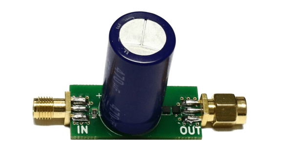
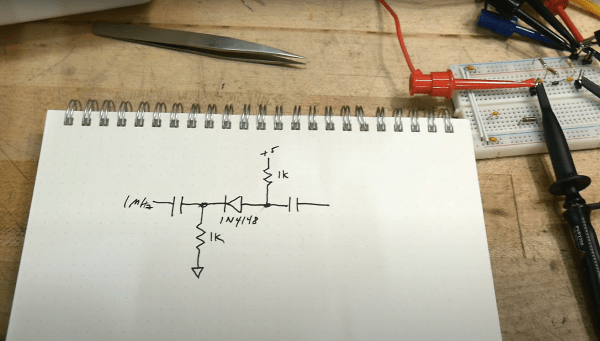
Or at least that’s what [Limpkin] discovered, which led him to design this low-frequency DC block. Having found that commercially available DC blocks typically have a cutoff frequency of 100 kHz, which is far too high to measure power rail ripple in his low-noise amplifier, he hit the books in search of an appropriate design. What he came up with is a  non-polarized capacitor in series followed by a pair of PIN diodes shunted to ground. The diodes are in opposite polarities and serve to limit how much voltage passes out of the filter. The filter was designed for a cutoff frequency of 6.37 Hz, and [Limpkin]’s testing showed a 3-dB cutoff of 6.31 Hz — not bad. After some torture testing to make sure it wouldn’t blow up, he used it to measure the ripple on a bench power supply.

It’s a neat little circuit that ended up being a good learning experience, both for [Limpkin] and for us.

Is A Diode A Switch?

Many hardware people around these parts will be familiar with devices used as switches, using at least three-terminals to effect this, an input, an output and a gate. Typical devices that spring to mind are bipolar transistors, triacs and and ye olde triode valve. Can you use a diode to switch a signal even if it has only two terminals? Of course you can, and it’s a tried and trusted technique very common in test equipment and circuits that handle RF signals. (Video, embedded below.)

The trick is that diodes block current in one direction but allow it to flow in the other, denoted by the deliberately obvious symbol. So your DC signals can’t swim upstream, but the same isn’t true for AC. Signals can be passed “the wrong way” through a diode by inducing small fluctuations in the current. Put another way, if you bias the diode into conduction, changes in the downstream voltage level result in changes in the current flowing through the diode, and the (smaller) AC signal gets through. But if you take away the bias, by turning off the DC bias voltage source, the diode switches back to non-conducting, blocking the signal. And that makes a diode a DC controlled switch for AC signals.

While [IMSAI Guy] demonstrates this with a signal diode, as he explains, one would typically use a PIN diode, which has an extra intrinsic (undoped) region between the P and the N, allowing the device to fully turn off, reducing leakage significantly.

Of course, we’ve covered diodes many times from different angles, there is always something to learn. Checkout how high voltage diodes are constructed, diodes detecting ionising radiation, and finally this great series about our new favourite two-terminal device.

See, the humble diode can be fun after all!

Continue reading “Is A Diode A Switch?”

Hackaday Prize Entry: A Better DIY CT Scanner

If you’re entering something in The Hackaday Prize this year, [Peter Jansen] is a guy you need to watch out for. Last year, he won 4th place with the Open Source Science Tricorder, and this year he’s entering a homebrew MRI machine. Both are incredible examples of what can be built with just enough tools to fit on a workbench, but even these builds don’t cover everything [Peter] has built. A few years ago, [Peter] built a desktop CT scanner. The CT scanner worked, but not very well; the machine takes nine hours to acquire a single slice of a bell pepper. At that rate, any vegetable or fruit would begin to decompose before a full scan could be completed.

This didn’t stop a deluge of emails from radiology professors and biomedical folk from hitting [Peter]’s inbox. There are a lot of people who are waiting for back alley CT scans, but the CT scanner, right now, just isn’t up to the task. The solution is iteration, and in the radiology department of hackaday.io, [Peter] is starting a new project: an improved desktop CT scanner.

The previous version of this CT scanner used a barium check source – the hottest radioisotope source that’s available without a license – and a photodiode detector found in the Radiation Watch to scan small objects. This source is not matched to the detector, there’s surely data buried below the noise floor, but somehow it works.

For this revision of a desktop CT scanner, [Peter] is looking at his options to improve scanning speed. He’s come up with three techniques that should allow him to take faster, higher resolution scans. The first is decreasing the scanning volume: the closer a detector is to the source, the higher the number of counts. The second is multiple detectors, followed up by better detectors than what’s found in the Radiation Watch.

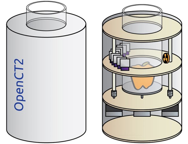
The solution [Peter] came up with still uses the barium check source, but replaces the large photodiode with multiple PIN photodiodes. There will be a dozen or so sensors in the CT scanner, all based on a Maxim app note, and the mechanical design of this CT scanner greatly simplifies the build.

Compared to the Stargate-like confabulation of [Peter]’s first CT scanner, the new one is dead simple, and should be much faster, too. Whether those radiology professors and biomed folk will be heading out to [Dr. Jansen]’s back alley CT scan shop is another question entirely, but it’s still an amazing example of what can be done with a laser cutter and an order from Mouser.


The 2015 Hackaday Prize is sponsored by:

Use A Cheap PIN Diode As A Geiger Counter

After the Fukushima nuclear power plant disaster, radiation measurement became newly relevant for a lot of people. Geiger-Müller tubes, previously a curiosity, became simultaneously important and scarce.

Opengeiger.de (English-language version here) has complete instructions for making a Geiger counter without a Geiger-Müller tube. Instead, this counter uses a PIN photodiode and some carefully chosen operational amplifiers. The total cost of such a device is significantly cheaper than the alternative: under $1 for the diode and around $5 for the rest. And since the PIN photodiode in question is used in many other devices, it’s not a niche component like a Geiger tube is.

The secret sauce is in component selection and tuning. Opengeiger uses the BPW34 diode because it is relatively common and has a large surface area, but also because it has a very low capacitance when reverse-biased. The first-stage opamp choice is also fairly critical. Considering that an average gamma radiation event produces only around 10 nanoamps for about 50 microseconds, a lot of amplification (100,000x), low noise, and high bandwidth are a must.

If you want to get started with this project, you could first browse through the explanation (PDF) to get an overview of the project’s goals, read up on all the technical considerations (PDF) or just head straight for the DIY instructions for the “Stuttgarter Geigerle” (PDF, schematic is on the last page). All of the documentation is chock-full of relevant references and totally worth the read.

THP Quarterfinalist: Low-Cost Solid State Cosmic Ray Observatory

There are a number of crowdsourced projects to put data from around the world onto the Internet, tracking everything from lightning to aircraft transponders. [aelias36]’s entry for The Hackaday Prize is a little different. He’s tracking cosmic rays, and hopes to turn his low-cost hardware into the largest observatory in the world.

Cosmic rays are protons and other atomic nuclei originating far outside the solar system. They hit the very top of Earth’s atmosphere at a significant fraction of the speed of light, and the surface of the Earth is frequently sprayed with particles resulting from cosmic rays. Detecting this particle spray is the basis for all Earth-based cosmic ray observatories, and [aelias] has figured out a cheap way to put detectors in every corner of the globe.

The solution is a simple PIN diode. An op-amp amplifies the tiny signal created in the diode into something a microcontroller can use. Adding a GPS module and an Ethernet connection, this simple detector can send time, position, and particle counts to a server, creating a huge observatory with crowdsourced data.

The detectors [aelias] is working on isn’t great as far as cosmic ray detectors go; the focus here is getting a lot of them out into the field and turning a huge quantity of data into quality data. It’s an interesting project, and the only one with this scale of crowdsourcing we’ve seen for The Hackaday Prize.

You can check out [aelias]’ entry video below.


SpaceWrencherThe project featured in this post is a semifinalist in The Hackaday Prize.

Continue reading “THP Quarterfinalist: Low-Cost Solid State Cosmic Ray Observatory”