With Arduino library support on an ARM Cortex M4 processor, it’s no surprise that we’re fans of the Teensy 3.1. And lately, [Paul Stoffregen] has been building out the Audio Library for this platform, making it even more appealing to the synth / audio geeks among us. And now, with just the addition of a highfalutin LED and some software, the Teensy can output digital audio over optical fiber.
S/PDIF, and more specifically optical TOSLINK, uses LED light sent down an optical fiber to encode audio data. The advantage of this over any voltage-level signals (like with regular wires) is that the source and destination devices aren’t electrically connected at all, which gets rid of the dreaded ground loop hum and any RF interference.
An S/PDIF audio data stream is a bit complex, but if you’re interested [Micah Scott] has a fantastic dissection of it up on her blog. Of course, you don’t have to know anything about any of that to simply use S/PDIF with the Teensy Audio Library.
We love open source hardware and software because of the collaborations that make ultra-rapid development of niche stuff like this possible. You can follow along with the development of the Teensy’s S/PDIF capabilities on the PJRC forum. Contributor [Frank B] modestly claims that “everything was already on the internet”, but that doesn’t make it any less cool that they got from zero to working library in a few weeks. (And note the clever use of a precomputed lookup table for speed.)
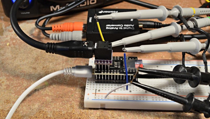
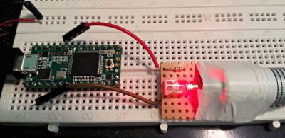 On the hardware side, [Paul] has posted up his adapter board for a cheap, but very professional looking, optical TOSLINK sender. But if you’re feeling ghetto, you can simply use a red LED pointed just right into the optical cable.
The end result? Lossless transmission of CD-quality audio from an Arduino-esque microcontroller, sent on a beam of light, for less than the cost of a latté.


This is so awesome. I love having the power of this chip on the teensy (I gushed about the use of DMA for the Smartmatrix library on my 1-pixel pac-man post). But of course the chip is only as good as the firmware running on it. Seeing the kind of work that Paul, Louis, and others are doing to build up rock-solid libraries to use the Teensy 3.1 peripherals is amazing. Great work!
paul asks about i2s to spdif chips. I like the wolfson chips, myself (wm8804 and 05). they are bi-directional so you can convert i2s to spdif or the other way around. they claim to have a reclocking fifo and in hardware mode they need only a single 12mhz xtal. software mode is a bit of a problem as 176k SR is not distinguishable from 192k and for high res audio guys (like me) that’s a problem. hw-mode avoids the problem but you have less control that way. you can also use the chip as spdif in and out, at the same time, to get reclocking benefit.
the cirrus earlier chips are jittery so I would avoid them.
the more recent TI asrc chips that are spdif receivers and i2s interfaces are supposed to be top-notch.
AK also makes very good spdif and i2s chips.
really; having spdif native on the controller is 2nd best; having a good clean i2s on the chip will GET you a good clean spdif from a dedicated hardware chip; and those chips tend to be very low-cost and mostly easy to use.
otoh, a lousy i2s can’t be fixed. if you have a jittery master clock, all bets are off.
there’s just a lot more to digital audio than pushing data bits around ;)
I was actually reading this yesterday as I was playing with Paul’s audio library gui tool. It is a cool hack to use the I2S hardware with the table lookup encoding.
Or if you happen to use a PSOC 5 you can just drag the spdif component into the project.
My experience with S/PDIF is that all devices I have have either an optical output, or a cinch input.
Which is an odd convention.
I guess this is for people with amplifiers with S/PDIF input though. Optical S/PDIF input that is..
optical and coaxial are just 2 different layer1 transports of the same data stream. coax tends to be half a volt, unbalanced on 75ohm coax. toslink is 5v ttl based. the only diff is the physical layer.
aes3 (aes/ebu from years ago) used 5v balanced 110ohm ‘xlr cable’ but again, the packet format is nearly identical to consumer spdif.
optical does have jitter issues, though, and optical is not really supported beyond 96k. I’ve had opto work at 192k but its not guaranteed. the toslink blocks (toshiba exited the market, sadly) are now hard to find and sharp is one of the few suppliers of them. still, the 25mhz parts are hard to find and so opto is a dead standard, going forward.
teh new hotness(tm) is usb audio. usb is 2 way (ack’d, flow controlled, etc) and can carry more info than simple spdif. usb has a new audio format (sort of new) called UAC2 (usb audio class 2) and that offers a ‘pull’ buffer model where the bit consumer (the dac) pulls data on demand from the host pc. the old uac model pushed data regularly to the dac and timing was part of that stream, which was a problem. uac2 solves that by having a local clock on the dac and the pc no longer is the time-clock master. the jitter level now is determined by local clock in the dac, where it really belongs ;)
finally, spdif has no real drm and so the industry would love to have it die off and force hdmi audio on everyone.
I still love spdif, myself; as its one of the only standards left that does not have drm, has bit-perfect transmission and is quite interoperable with lots of gear. usb/spdif is not hard, these days, and spdif is still the main way into dac boxes (until usb audio finally takes over the world).
FYI: One of the links on the website point to digikey’s page for $1 at QTY 1 for 16Mbps part.
http://www.digikey.com/product-search/en?x=0&y=0&lang=en&site=us&keywords=1080-1434-ND
Optical over plastic fiber isn’t dead it has just been moving primarily to a different market. MOST(protocol) used in cars and in industrial areas it is used to isolate noise prevent electrical shorts. It is also faster to connect up then many electrical connections and easy to troubleshoot by shining an led in one end.
for audio use, its being killed off. the industry does not like bit perfect audio ‘in the clear’ on simple cables. they like interwoven drm audio and drm hdmi video interwoven so that you can’t easily break each stream out. this was done on purpose. evil… ;(
its a fact that plastic toslink fiber is not meant to go beyond old redbook audio standards; and some even argue it was never up to even THAT task.
for a while, sony was a big fan of coax and their cd players had the famous orange rca jacks on the back. later, they moved over to toslink and the coax jacks mostly went away. philips was into coax, too, in the early days. some vendors picked one style and some picked others, even flopped back and forth as they tried to ‘choose’ a media format for transmission.
I recently bought a handheld 24/192k audio player and its digital out is copper based, not fiber. it does actually play at 24/192k and does not convert down. supports DSD files, too, fwiw. because its marketed as high-res audio, its digital out HAS to be coax. again, toslink is not really spec’d beyond 96k and even 96k is pushing it.
for usb audio dongles like the turtle beach ‘advantage’ dongle, its line-out is analog for TRS mini and also opto for spdif digital. it does not do high res, so 44k and 48k are the only formats it supports; and because of that it can get away wtih using those convenient combo opto+analog jacks. you won’t find those combo jacks doing 192k, I’m pretty darn sure of that.
any new non-low end audio device that has digital i/o will need to support high res and that means that opto eventually goes bye-bye. get used to that fact.
Optical doesn’t work with beyond 96k?
I’ve used ADAT machines with 8 channels of 16/48k over a single plastic TOSLINK cable (later ADAT machines could do more bits): Verified bit-perfect, zero issues.
Availability of high-frequency TOSLINK assemblies? Scour old motherboards: The one I write this on is old enough that I get a lesson in energy efficiency whenever I write about it, and it (annoyingly) has TOSLINK and 24/192k support (which seems to work fine with a TOSLINK to coax adapter and about 50 feet of RG-6 to my AVR).
Meanwhile, optical has exactly the same jitter issues associated with it as coaxial and AES/ABU do: None of these have a dedicated clock included in the signal, and the clock recovery techniques are identical between all of them.
Finally, S/PDIF bitstreams can have DRM associated with them, though it is increasingly unlikely to affect you as time marches on. (Google “SCMS” for a history lesson. But in short, SCMS was jointly created by Sony and Philips for the purpose of eliminating serial lossless copying — the same Sony and Philips that are the “S/P” part of S/PDIF.)
Isn’t USB a bit laggy in response for realtime audio? You seem to be informed, do you know if that plays at all?
you have enough buffering and reserve bandwidth so that you don’t under-run, so its not a hard problem. usb2 is way fast enough for high res audio and as long as the end device can get data from the host as it requests it, it can clock out of it (the dac’s) fifo and all is well. that’s the elasticity that makes it mostly resistant to host lag or jitter issues.
as long as timing is not part of the data itself (spdif embeds timing with data, which is the problem), then the old ‘bits are just bits’ argument is valid. that’s the usb UAC2 style.
UAC1 is not ‘bit are just bits’ since timing does derive from the host (cpu) clock and if that jitters, the downstream device has a harder job trying to clean it up, if it even can.
the SCMS stuff was a form of drm, its true. it was not hard to defeat (there was a mailing list called ‘dat-heads’ many years ago and a common subject was scms removal) and it was totally defeatable on ‘pro’ decks; and anyone who could afford $1k could buy a pro deck, so scms only kept the poor folks from copying bits.. and that only lasted until the first spdif ISA pc cards came out; from then on, scms became strippable ‘as a side effect’ of importing data into a pc (lol).
as for my comment about toslink and 96k, I’m saying that its the highest ‘supported’ bitrate. as I said, I’ve personally run 192k over toslink with proper opto blocks as well as the crappier ones. it mostly works, but its still running quite out of spec. if you win, you win; but its not guaranteed to work and certainly not all opto blocks you see on gear will run even up to 96k well. you take your chances on opto; but coax style works at any rate.
shameless plug for my DIY project: I built an spdif ‘meter’ that shows the samplerate in big LED numbers. it uses the arduino, the freq-counter software library and an spdif->i2s converter board so I could grab wordclock from the i2s breakout. wordclock is your bitrate, so if your audio runs at 44.1k, you should see 44.1khz wave from wordclock (aka ‘left-right’ clock). its as simple as getting the 3.3v wave from the i2s chip, buffering it for the 5v arduino and having the arduino count freq and display the SR that is closest to the measured value. my box also has a switch function so you can select the input, just like any normal switch.
https://farm8.staticflickr.com/7641/16619260324_e37dacf33b.jpg
(I plan to enter this in a HAD submission, but it still needs a bit more sw cleanup before its ready to be posted. it will be fully open source in hw and sw).
@bl – which “freq-counter software library” are you using? If it’s FreqCount (the one which doesn’t require a kludge factor for accuracy), that’d be a really interesting “full circuit” kind of situation… since I’m the author of FreqCount, and also the author of the Teensy Audio Library… although Frank B deserves most of the credit for the S/PDIF addition.
While we’re talking of shameless plugs, I hope you’ll use Teensy if you’re using FreqCount, partly because I’m the creator of Teensy, and partly because sales of Teensy funded development of FreqCount and FreqMeasure (and many other libraries), and partly because Teensy has a more accurate crystal than most other Arduino boards.
With a 3 digits display, I would doubt you’ll be able to spot a difference for frequency count may be except for one that uses internal RC oscillator that has a percent or more inaccuracy.
I have not tried the everlight units. I forgot, yes, there is a source beyond sharp (brand). the TOTX and TORX parts from tosh, though, are drying up ;(
good news is that coax is fine, it can be isolated (in fact, it should be trafo isolated on both sides), its lower jitter, does not have a huge parts count and can run past 192k. lots of vendors skip the spdif pulse trafos and its a shame, but as long as one side of the link has one, you are still isolated.
This is really cool, I love the just using a red LED thing!
Does anyone know anything about the in car audio optical “MOST” bus used in German cars like BMW, AUDI and Porche?
It seems to connect up head units, amplifiers, CD changers, bluetooth recievers etc.
A few now mostly discontinued devices could emulate MOST bus CD changers, I’d love to do that but cant find almost any info. The closest I’ve come across is a $600 dev kit for a chip that’s unavailable in low qty and not sure comes with any documentation.
I’ve seen speculation it’s just spdif extended to support commands like change track as well as audio.
Doesn’t help that “MOST BUS” isn’t a very googleable name.
Not that hard, there is wikipedia https://en.wikipedia.org/wiki/MOST_Bus
And a search for “Media Oriented Systems Transport” (instead of MOST) immediately landed me this pdf with a description:
http://www.cse.chalmers.se/~svenk/mikrodatorsystem/lectures/MOST_ppt.pdf
Which has the timing and description of bitrate and all.
Indeed but I guess that everyone writing about MOST won’t write out the full name.
I’ve seen that PPT and it’s a great help for the software side, but I’m struggling to find how I can at least prototype the hardware side for a reasonable cost. If I could do it with one or two teensy (the MOST bus is a loop and each device needs to pass on messages to the next) that would be great.
I know a lot about it and although I’m often surprised of what the maker community can come up with I would say that the MOST bus is not accessible to it. The challenges include:
* Very hard to source and expensive components. (Maybe you can find them trough a chip broker)
* The documentation (e.g. datasheet and chip API) and firmware is only released to customers under NDA
* The network stack that you need to interface other units in a robust manner caries a very high license fee.
* The development tools (e.g. network sniffers) costs thousands of euros.
If the end goal is to interface a car you would also have difficulties to reverse engineer the OEMs proprietary protocols that resides on top of MOST. Many cars also include DTCP content restriction.
Further, MOST is expected to be replaced by Ethernet in many future infotainment systems.
There’s a book that’s free to download on the MostCo site if you are interested, it is a good read to understand the challenges that MOST addresses even if you aren’t planing on actually building something with MOST.
http://www.mostcooperation.com/publications/most-book/
Thanks, that was pretty much what I’d worked out, but had hope there was more info about the protocol and network stack out there that’s not under NDA! Or at least some way I can start a reverse engineering effort without spending loads of cash.
I might just go lower level to interface the stuff I want. E.g interface with the steering wheel switches directly and replace the amplifier with an off the shelf one, then mix in the car amp for the bings and reversing sensors. Only loose end is the head unit controls and the LCDs.
Agree that MOST is being replaced, but still a lot of cars out there with it.
Here is some open information that you may find useful
http://ww1.microchip.com/downloads/en/DeviceDoc/DS60001264A.pdf
This PDF also contains references to the restricted documents, maybe it is possible to find them by searching for the document names (e.g. DS81110AP5 and UM_OS81110_INIC_API for the OS81110 INIC data sheet and API). Maybe also by contacting Microchip with a credible story.
If you truly are thinking of an effort to reverse engineer the bus I recommend you to read the book to find out what kind of communications that goes on between INIC and EHC (e.g. setting up audio sockets and sending control messages). It will help to know about the states that exists in the IC (e.g. figure 3-8 in the PDF above).
After that I would recommend that you find a unit to study in a running system, the simpler design the better. Look for a unit where the control messages are sent to INIC over I2C and the audio isn’t sent using MediaLB.
Note that the INIC contains an “INIC Configuration String” as well as firmware, the configuration string is typically specific to the product and controls low level behavior (like pin configuration, time parameters and bus frequency). So, if you find the chip from a chip broker you still need to flash the configuration string if you would like it to behave as the IC in the device you are studying. Developers use the INIC explorer tool and software for that but if you can get a hold of a software update of your car that includes the INIC you are studying you could capture the communication with the IC during the update. It is also possible to read it out if you have the API.
That said, I would think that the effort required to reverse the system is bigger that building a new open communication system for cars. AD2410W is an interesting IC if you are looking for digital audio transfer, but SPDIF would probably do too in many cases.
http://www.analog.com/en/products/interface-isolation/automotive-interfaces/automotive-audio-bus/ad2410w.html
Thanks that’s really helpful, I’ll look through the binary firmware updates of some of the third party devices that already speak MOST. Hopefully they’ll have some hints.
Hello friend.I search in the http://www.microchip.com/ , but I can’t find DS81110AP5 and UM_OS81110_INIC_API you said above.Do you have DS81110AP5 and UM_OS81110_INIC_API ? I look for it several days,where can I get them?
There really should be a wikileaks for NDAed tech pdf’s.
“dreaded ground loop hum”
I have a major case of that. Analog out from PC to amp in a different room, around 7 meters away. Can’t use sane power outlet. Have tried putting a cheap “ground loop isolator” on the analog cable which only helped a tiny bit.
PC has spdif out so this post got me thinking. Can anyone recommend a good but very cheap spdif optical in DAC? Have seen a few on eBay but it would help if anyone with experience could recommend one.
http://www.digikey.com/product-detail/en/PLR135%2FT6/1080-1435-ND/2693965 receivers $1.84 each QTY 1. Their transmitters are $1 a piece.
I haven’t used the digikey ones, but the ones I got off ebay 10 years ago worked. 1 of the transmitter went dark very shortly.
The digikey parts are legit and have datasheet, so I would recommend them based on that.
I bought a random one from Amazon for testing this code. You can see if in the photo. There are tons more just like it on Ebay and lots of other sites.
I’m certainly not an audiophile, but I did listen to it through decent quality M-Audio monitor speakers, which you can also see in the photo above. Its analog output level is set a little too high, so a 0 dB signal causes it to clip somewhat. But if you keep the levels just a little lower, it sounds really good.
If you want professional or audiophile grade, then you probably would want to use something like this board, which is still in development:
https://forum.pjrc.com/threads/27215-24-bit-audio-boards
I believe 6 of those bare PCBs are still up for grabs (see msg #94-96 and #117 in that thread). But it’s a complex board to build with a LOT of parts. Such is the cost of “no compromise” audiophile design…
Oh. I missed the part about the DAC and not just opto receivers.
That DAC PCB from the layout picture looks reasonable except for the AC coupling caps at the opamp inputs. I would stay away from ceramic caps as AC coupling and feedback circuit as the wrong types (anything outside of NPO/C0G) which happens to be large values, can have piezoelectric effects.
the wolfson 8741 (and similar) series are very good dacs. you should be able to find ebay/china dacs that have that chip for low cost.
another good one is the AK 4399. highly recommended as a pretty damned good (high end) dac chip.
I avoid ESS dacs unless its their flagship and even then many designers don’t do it properly. low-end ESS is total junk (gibbs issues galore).
low-end TI is also junk (same gibbs clipping issue).
crystal^Hcirrus has the famous cs4398 and while its a bit old, its still considered their best non-wolfson (after the merger) dac and you can get those boards from ebay cheaply.
finally, there are many diy dacs that you can build. I am associated with amb.org (amb labs) and I can recommend his dac kits and designs (see his website). he sells pcb’s for reasonable prices, pcb’s are usually 4 layer and made in the US by a top pcb fab company (NOT crap from china). the gamma2 is a good affordable dac using wolfson’s best chip, also using ti’s asrc chip and can be run from simple usb 5v power. will be better than most anything you buy from china, as you get to pick your parts and you won’t end up with fakes, that way.
hth
@paul: I didn’t know you were the original author of freq count! the one I use is from here: http://interface.khm.de/index.php/lab/interfaces-advanced/arduino-frequency-counter-library/ (are they the same? I have not checked but I have been using that one from .de for a few years, now).
accuracy is actually not important since I’m only showing the -nearest- standard freq in spdif. my display is not to show how far off from exact freq the spdif stream is, but to -identify- what sample rate it is, and for that, you only need a very rough guess. if the ‘measured’ value is within 10% or so of 44.1, I declare it 44.1 on the display, and so on.
I also did purchase a teensy 2.0 a long time ago from you but sadly never did anything with it. while I like your work, I just cannot afford the unit prices your modules cost. wish I was a bit richer, but I’m just not, and so I’m ‘stuck’ using crap china ebay modules such as the nano. its nowhere near as nice as your stuff, but I just don’t have the money (or a job/income right now, to be honest) so I cannot afford the higher priced (and admittedly better) controller modules.
I didn’t write that “labIII” one. In fact, the main reason I wrote FreqCount and FreqMeasure is because those older ones have inaccuracy that requires the “calibration” step, even if your board has a highly accurate crystal. Well, and also because they aren’t portable to other timers, even within AVR chips. FreqCount works on nearly all AVR-based boards (not only Teensy) and it has a good abstraction layer to allow porting to other non-AVR processors. But it sounds like your project doesn’t need accuracy, so the small error due to the software delay in restarting the gate period is probably fine for your use.
It works even without the external LED: A wire between Pin 22 and PIN 13 is sufficiant !
This way, PIN 22 (S/PDIF out) drives the onboard-LED. The Lobboard ED is not as bright, but the light is just enough .
Did you know, that with SPDIF the Teensy is able to play Dolby Digital 5.1 *.wav without any change ?
Try this example withe the audio-library-waveplayer: http://www.diatonis.com/downloads/diatonis_ac3_wav_anfos.zip