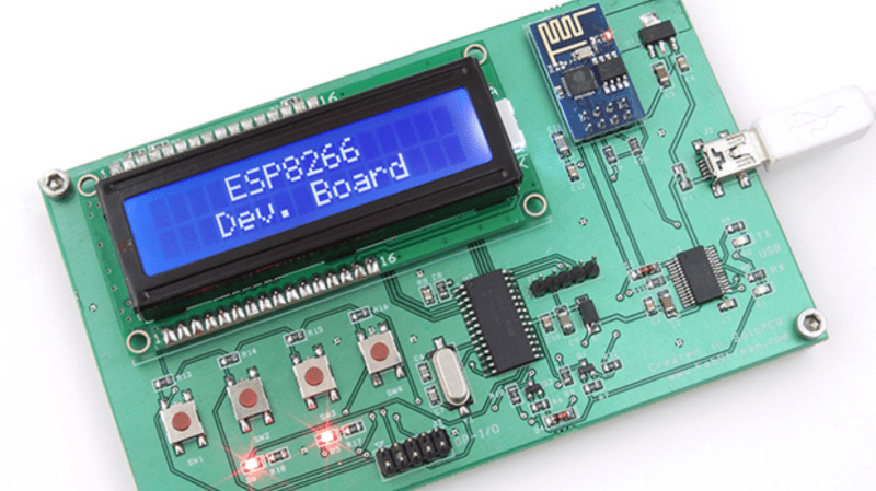
Those small, super-cheap, ESP8266 modules are being installed everywhere, creating all sorts of frivolous internet connected thingamajigs. But consider this period as a training ground of sorts, as hackers smarten their chops on figuring out how to get the best out of this IoT gravy train. Right now, getting the ESP8266 to work requires a fair amount of work and to make things easier, [Abdulgafur] built a ESP8266 development board.
The dev board lets the user connect the ESP8266 to a PIC micro controller as well as to a host PC. In addition, it hosts several peripherals such as a 2×16 LCD display, 4 push buttons, couple of indicator LEDs and some GPIO’s broken out to a header. PC communication is via a FT232RL USB-UART converter over a Mini-USB connector. There’s also a few bi-directional level converters to translate between 5V and 3.3V and pull-up resistors for the ESP8266.
As of now, the dev board only supports the ESP8266-01 module. A nice upgrade would be to add support for other ESP8266 modules too. Maybe a separate, 3d printed, pogo pinned, test fixture for the other modules. If you plan to build you own version, [Abdulgafur] has the schematic, PCB and BoM available for download, although we couldn’t spot the PIC code, so you might have to ask for that. And it would be a good idea to remove the GND copper pour from under the ESP8266 footprint.


Here’s a cool little ESP board I found the other day for $3.80. It comes with an ESP-12E module-
http://www.aliexpress.com/item/ESP8266-serial-WIFI-industrial-grade-stable-version-of-the-test-plate-full-Total-IO-extraction/32242633472.html
Add a USB to TTL UART module for $0.95 –
http://www.aliexpress.com/item/1pc-lot-USB-to-TTL-UART-module-CH340G-CH340-3-3V-5V-switch-30502/32258627657.html
Add a serial LCD for $2.35 –
http://www.aliexpress.com/item/1602-16×2-HD44780-Character-LCD-w-IIC-I2C-Serial-Interface-Adapter-Module/2028071847.html
And a few buttons and you are in business.
This one has already a lot of peripherals (Button, relay, buzzer, DHT11, RGB LED, …)
http://www.aliexpress.com/item/1PCS-ESP8266-Wireless-Wifi-Module-Develop-Board-8266-SDK-Development-Chip/32266318927.html
Heh, add a morse code key and you’d have one of those electronics educational kits, like the ones with the little springs you bend to insert wires. You could make a doorbell, burglar alarm, crystal radio…
So this is a PIC development board that happens to have an ESP module on it? When I first started reading I thought it was for ESP8266 development. Why not use an ESP-07, ESP-12 or ESP-201 with more IO lines native to it? The ESP 01, 07, and 12 are all about the same price now.
Yeah. It is an old PIC as well. Electro Labs seems to like the PIC18F252 though as most of their projects use it.
I would have hung the ESP’s antenna area over the edge of the board. the ground plane is only going to hurt antenna reception and transmission. the ESP is not very strong, as it is.
otherwise, looks fine and is probably fun to use.
I wonder how long the ESP will continue to use that ‘odd’ pinout? can we really count on the 2×5 pin grid or will that just be one of the many form factors we will have to deal with?
and of course, some new hotness could be out in months time and then everyone turns their attention to THAT platform.
things change very fast, and in the time you design a board to use a module, there could be a new module that is even better and yet not pin compatible.
Another alternative I found and had delivered yesterday is the Cactusduino board
https://www.tindie.com/products/AprilBrother/cactus-micro-arduino-compatible-plus-wifi-esp8266/
Where can I download the .hex for the PIC ?
[…although we couldn’t spot the PIC code, so you might have to ask for that.]
Sorry, but this one can be considered eventually as a PIC development board. Hardly. Development board means something else than I can see in description there.
It’s more a application board. A very limited one. With some Wifi capabilities using a ESP module. A lot of marketing stories around there.
This one can be considered as a ESP8266 Development Board:
http://www.esp8266-projects.com/2015/04/esp8266-ultimate-devboard-finally.html
Features:
18 bit ADC
12 bit DAC
Voltage Measurement
Current Measurement
Temperature Measurement
Real Time Clock
High Resolution LCD Display
User Definable Buttons
On Board 3.3V Regulator
Looks like something different than above?