When you’re looking to add some wireless functionality to a project, there are no shortage of options. You really don’t need to know much of the technical details to make use of the more well-documented modules, especially if you just need to get something working quickly. On the other hand, maybe you’ve gotten to the point where you want to know how these things actually work, or maybe you’re curious about that cheap RF module on AliExpress. Especially in the frequency bands below 1 GHz, you might find yourself interfacing with a module at really low level, where you might be tuning modulation parameters. The following overview should give you enough of an understanding about the basics of RF modulation to select the appropriate hardware for your next project.
Three of the most common digital modulation schemes you’ll see in specifications are Frequency Shift Keying (FSK), Amplitude Shift Keying (ASK), and LoRa (Long Range). To wrap my mechanically inclined brain around some concepts, I found that thinking of RF modulation in terms of pitches produced by a musical instrument made it more intuitive.
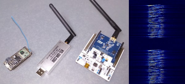
And lots of pretty graphs don’t hurt either. Signals from two different RF dev boards were captured and turned into waterfall and FFT plots using a $20 RTL-SDR dongle. Although not needed for wireless experimentation, the RTL-SDR is an extremely handy debugging tool, even to just check if a module is actually transmitting. Continue reading “RF Modulation: Crash Course For Hackers”