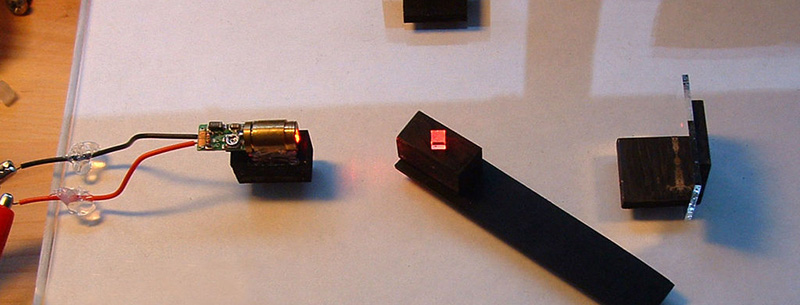
[jrcgarry] hacked together this awesome interferometer which is able to measure displacements in the nanometer range. Commercial interferometers are used in research labs to measure tiny displacements on the nanometer scale, and can cost tens of thousands of dollars. [jrcgarry] used beam splitters from BluRay drives, mirrors from ebay and a 5mw laser diode.
We’ve covered the use of interferometers before. But never an instrument built from scratch like this. Interferometers exploit the wave-like nature of a beam of light. The beam is split and sent down two separate paths, where the beams bounce off mirrors to return to the beam splitter to be recombined. Because of its wave light nature the beams will interfere with each other. And as the beams have traveled different distances they may be in or out of phase. Resulting in either constructive (brighter) or destructive (darker) interference.
Because the wavelength of light is on the order of 100s of nanometers, by observing the interference patterns you can monitor the displacement of the mirrors with respect to each other at nanometer resolution. [jrcgarry] doesn’t use the interferometer for any particular application in this tutorial but it’s a great demonstration of the technique!


The question now is can we combine this with an inexpensive CNC machine or 3dPrinter possibly even replacing stepper motors with brushless motors.
I think the first question is can we get a low cost axis of motion that moves straight enough to not cause problems with the laser / mirror alignment to cause interrupts in feedback (and loss of absolute position). The mention of 1/2 hour of playing with the mirrors to get them to cause the interference fringing is worrisome.
I was able to do this without much fiddling.
I glued 3 small magnets to the back of the mirror, then threaded 3 long screws through a piece of aluminum plate. The magnets stick to the screw ends, allowing easy adjustment of the mirror in any direction.
The big issue is vibration. Mount everything on heavy blocks, put the whole thing on a big slab of rock, and don’t bump the table while adjusting things.
A microscope slide as a beam splitter works just fine.
(I was able to send one leg of the beam down my hallway and back, making for a rather large time difference between legs.)
I’ve setup a place where we can continue this discussion:
https://hackaday.io/project/5283-potpourri/log/21475-laser-internferometry-discussion
I’ve got some hands-on experience with interferometers, and I’m a physics guy, so I’ll try to answer questions about this. Others have experience with CNC mechanicals, so let’s float some ideas and talk about them.
how did you use a microscope slide to spit the beams ?
Commercial setups use cube-corner reflectors which makes alignment much simpler.
Interferometers are highly sensitive to vibration. Any tap or knock on the table holding the device will scatter the interference pattern for a few moments until the vibrations settle down.
It would be almost impossible to use an interferometer on a machine that uses steppers or CNC machining.
Even if you made measurements after shutting down the machine (periodically during the job, for instance), you wouldn’t be able to tell where you were. Interferometers measure differences, so you need to count the fringes as they pass by while the device is moving. If you don’t keep track of the count while moving, you don’t know where you are when you take the measurement.
I’ve built an interferometer at home for measuring piezoelectric element displacement. It works fine, but you need a remote power switch for the laser because the vibration of touching the switch will scatter the pattern.
(I put a square wave into the piezoelectric element, and adjusted the voltage so that each step of the wave corresponded to 1 fringe. IOW, I started with a low voltage and saw the fringes move a little with each pulse, then adjusted the voltage until the fringe moves over to the next fringe at each pulse. Knowing the voltage and wavelength of the laser, I calculated the displacement per volt of the piezoelectric element. A cheap laser pointer works fine for this.)
That sounds like it’d function a lot like a really precise rotary/optical encoder on that axis then? That’d be really nice for positioning but it’d bring with it all the problems of missed ticks and everything else. Solvable but then I also wonder about overshoot and how well the other axis might hold position with a brushless motor.
The interference pattern forms vertical alternating light/dark stripes. (It’s more complicated, but this is a good beginning explanation.)
The stripes are the interference between the waves from each path coming together. Where the crests match up you get a bright band. Where the crest matches a trough, you get a dark band. Since there is a slight angle difference across the viewing area of your target screen, you get slight differences in path length which results in the light and dark bands.
As one path gets longer or shorter, the stripes move left or right. You count the stripes as they pass by, and each stripe distance is one half of a wavelength difference in length. (Because moving the mirror 1/2 wavelength adds 1 full wavelength of total travel.)
You can get wildly accurate measurements using this system. For example, put two light sensors on either side of a band, and hook them up to a galvanometer that adjusts the mirrors. Set negative feedback so that the galvanometer adjusts based on the difference in measured light.
In other words, the band is kept centered between the two sensors. If one sensor measures more light than the other, the galvanometer moves the fringe to become more centered. The feedback voltage is then the signal to be recorded.
[I haven’t done this, but] I suspect you can detect differences of 1/512th of a wavelength positioning without much trouble. Depending on the wavelength of your laser, that’s in the angstrom range. At that resolution, you can easily measure the gravitational attraction of the moon, most earthquakes, and all the trucks that drive by your house.
I’ve setup a place where we can continue this discussion:
https://hackaday.io/project/5283-potpourri/log/21475-laser-internferometry-discussion
I’ve got some hands-on experience with interferometers, and I’m a physics guy, so I’ll try to answer questions about this. Others have experience with CNC mechanicals, so let’s float some ideas and talk about them.
“1987 LIP 101 exposed interferential linear encoder, measuring step 0.02 µm”
– http://www.heidenhain.com/en_US/company/history/#c24
This linear encoder was for CNC machines. The tech has been around for a long time.
Piezoelectric actuators tend to get used with these things. Perhaps one could use them to dynamically dampen or stabilize an optical bench.
Regular linear encoders or LVDT’s are used all the time on active isolation systems. I know a prof that has a FIB that has that, when a truck passes you can see the bars on the controller respond.
Reading up on that. Much obliged. :)
Use IR so the wavelength is more manageable. Read – if you can find them – Robert Forward’s papers from Hughes Research in Malibu from the late 1960’s/1970 about using piezo to control noise in interferometers. He was working on gravity wave detection and his rotating gradiometer (see “Gravitation” by MTW). In fact he made sub-angstrom measurements by dithering the mirror position. I have the papers somewhere.
I’d love to try measuring the displacement of the piezo electric actuators I have. Did you write up your interferometer rig anywhere? I’ve been considering buying a cheap commercial system, but a cheap homebuild is obviously attractive and would be interested in hearing more about the issues you faced.
Contact me on .io (user PWalsh) and we can chat.
Interferometers are often used for position feedback on SEM stages, giving nanometer positioning resolution with (I believe) stepper motors.
It would not be the well ballanced system, if you have 1 nm accuracy for head positioning, and the tool error of 10,000+ nm.
That’s why you need something like air bearing or flexure plate linear movement and high accuracy high precision linear actuation, piezo or ultra high precision ball screw. Dan Gelbart has an air bearing lathe with micrometer accuracy that he posted on youtube that I wonder if it uses these or just trial/error to make accurate parts. After reading a bit I realised the comment below mine includes something about gelbarts lathe too.
These mirrors are in all optical disk drives, but extracting them is a little tedious. If you look to buy half-silvered mirrors online you immediately get into optics-grade pricing. This hacker bought one from a blu-ray drive, presumably because people dismantle them for their lasers.
Meanwhile, the use of optical media in PCs has dropped with the spread of broadband, so one might imagine that the machines which made CD-ROM drive components will be sold as used industrial equipment, or a new sensor for smartphones will emerge.
The hacker mentions a bad, plastic optical bench. – After some research, I theorize that that an air bearing or a hydrostatic guide rail would suffice to isolate the interferometer from the kind of noise that is too difficult to filter in software.
https://www.youtube.com/watch?v=sFrVdoOhu1Q
Dan Gelbrat who was recently featured here on HaD uses air bearings in his custom-built CNC lathe. A HaD post on air bearing hacks would be much appreciated.
Some open questions I’d like answered:
Does one need to isolate the airflow from a scavenged AC-unit scroll compressor from the air bearing to keep acoustic vibrations in check? Can one use a propane tank to store the air, and does need pressures which approach the tolerance of both the tank and the compressor (30 bar)?
If one needs pressure above 8 bar, how can one make this set-up not dangerous and recklessly indifferent to one’s neighbor on the other side of the wall?
How much humidity can one expect an intact & cheap AC unit to remove from the air during its dry-cycle?
What sort of oil can I use for a scavenged compressor and how does one keep it in the compressor?
Do air bearings work with leadscrews, or does one need linear electric drives?
Here’s some background information you might want to consider.
When I was doing this back at uni, we made a cheap optics setup using a wooden box filled with sand, sitting on an inner tube.
The sand was there simply for mass, and allowed us to easily set the optics in any position or height (but we still needed adjustment screws). I don’t recommend the sandbox, but it works. Big polished slabs of rock are easy to find nowadays.
My point is, you can get a sufficiently damped platform by mounting a heavy block (metal, slab of rock, etc.) on an air-filled tube. This would be much simpler than working a compressor, and also corral the system sideways. You can get an inflatable mattress on eBay for about $20. For long term, inner tubes (the big, truck-style ones) will hold pressure for a long time.
Also, I’m told that an AC unit compressor requires internal lubrication supplied by the refrigerant gas, and will quickly die if used on regular air.
Also also, 8 bar (ie – 8 atmospheres) is wildly more than you need. An inner tube with 1 PSI gauge (1/15th of an atmosphere) contacting the table in a square 10 inches on a side (= 100 square inches) would hold (1 PSI x 100 square inches) 100 lbs. You don’t need much pressure if you have a lot of surface area.
(I once bet my coworker that I could raise the end of his jeep off of the ground using my shop vac and a garbage bag. I won that bet.)
Nice tip about the sand! I was thinking about pouring a slab of concrete, but that would not exactly be portable.
For a flat surface, I’m considering the thickest piece of glass I can find. – Now with sand I presume I could ‘float’ the glass on the sand by vibrating the sand strongly, making the bed settle absolutely horizontal. :)
This however does not isolate machine parts from each others’ vibration… For that I’m probably back to leadscrews through air bearings, and then surface area goes down a lot. If I want to machine metal, that means I’ll need higher pressures. =\
The upside should be that one can use cheaper leadscrews; perhaps even retrofit an old lathe.
That’s not the kind of air bearings he is referring to, he is referring to air bearings that are used on linear slides. They usually use quite high pressure.
I’ve setup a place where we can continue this discussion:
https://hackaday.io/project/5283-potpourri/log/21475-laser-internferometry-discussion
I’ve got some hands-on experience with interferometers, and I’m a physics guy, so I’ll try to answer questions about this. Others have experience with CNC mechanicals, so let’s float some ideas and talk about them.
Ill take a shot at your questions.
First, I would not consider using an AC compressor for an air compressor, at least not of any significant duty. They were designed to circulate the oil though the system to lube the pump, when you dead end the pump into a tank you will loose all the oil and you kill the tank. Don’t use a propane tank, there are no overpressure valves and they are just not intended for it. If you need a quiet compressor look for a used Jun-air or other dental compressor on craigslist. I picked up a nice jun-air for $100, it is very quiet, sounds like a refrigerator running. They use a variant of an AC compressor that is designed to lube itself.
The higher the pressure you pump to the less efficient the pump is and the lower volume you get out of it. Also it wears on the pump more.
Air compressors concentrate the water vapor in the tank which condensed on the walls and starts building up. So you will start with dry air and it will get wetter and wetter as you go along. This is another reason not to use a propane tank, you need a drain of some sort.
Home made air tanks are bombs waiting to happen. Just dont do it, buy a pre-made hydrotested tank.
Air bearings work with lead/ball screws.
Jun-air seems like a very good choice, provided that 8 bar pressure is enough… If not, then the prices seem to just sky-rocket, and I’m back to researching oil filters and the 500 degrees Centigrade creep factors of unknown grades of steel. – You know, you can get 99 deg C thermal relays from old microwave ovens…
I seem to remember someone saying that Dan Gelbart spent 2.5 million USD on his lab. If I had the kind of money that let me spend a million USD on just myself, I’d build one of those too. If there was a get rich quick scheme that anyone could do, then there would be no need for young men to risk their lives on the many misadventures of life.
Call me jaded; all my life I have been told what _not_ to do at every turn, discouraged, so it should be little surprise that I have not accomplished much.
Found hydrostatic lead screws being sold by German companies. Vibration-isolating effect advertised.
Much higher pressures can safely be used with hydraulics than with pneumatics, so there is much less to worry about.
CNC Machinist & watchmaker very interested in this discussion. Will check out the .io of this later on.
Jun Air compressors are the only quieter compressors I know of. Professional watchmaking industry uses
them alot with micron filters at the watch bench for sucking up micro debris in watches. Very expensive new.
If you don’t know about what goes beyond ground ballscrews in positioning accuracy- it’s not called a
hydrostatic lead screw. I believe they are called Hydrostatic ways, because there is no screw. Think of
an incompressible oil filled bellows that moves in 0.00001″ increments or better using oil bladder flows
through valves. Kern is a German company that makes incredible CNC machines with jig grinder attachments
and laser tool measuring options that use this technology. As far as I know, hydrostatic way tech is the very
highest pinnacle of all current positioning technology for actual machining use.
That said, don’t think they could be made by normal even dedicated makers. Not sure. Would love to have a
Kern Pyramid Nano mill, or a way to use this interferometer for a manual jig borer of custom make for making
watch plates with ludicrous accuracy.
S.O.aB! Will someone please tell me how to get rid of this damn formatting?
I’m tired of my posting format making me look an idiot! It only happens on HaD!
Thanks for those references Drew! I looked at a video presentation of the Kern Pyramid and they show hydrostatic pressure measured at just below 30 bar. =)
Also, very interesting to know that watchmakers could use these kinds of machines. Seems to me MEMS would be related too, somehow…
Ganzuul,
Normally, watchmakers are not machinists. Especially not CNC/newer tech using ones. I’m both :) Kinda rare,
but I worked as a machinist before learning watchmaking. I do both now.
I don’t use one for my work, I use a normal manual lathe and mill. Small ones. But there is a watchmaker that
started his own company with I think some partners, and they use a Kern Pyramid Nano for some of their work.
I actually discovered Kern and hydrostatic ways thanks to finding out about his work. Google Paul Loatman.
1) Due to the restriction of the air bearing (especially in orifice type air bearings IIRC) you won’t have any issues with vibrations from the compressor, a regular shop air compressor should be suitable enough. I’ve used propane tanks to increase the capacity of my air compressor, but especially with the high precision air bearings you’d be using, even a smaller air compressor you can pick up by hand should supply enough from the compressor part itself, even without the tank. Too high of pressure can actually contribute to vibrations in the bearing (different than vibrations from the compressor, more closely related to the spring effect of the air pocket. Most air bearings are between 45-90psi as far as I’m aware.
2) You’d have to get in touch with a specialty compressor product manufacturer to get a better answer but you can buy higher pressure fittings on ebay and other places online.
3) Scavengers and filters for air compressors are affordable and easy enough to use that I wouldn’t worry too much about how much an ac unit can help.
4) Mentioned in another post if you really do need to know.
5) You can use any type of linear actuation so long as you’re aware of each’s limitations and benefits. Ballscrews may transfer some limited vibrations from their movement but I doubt it would be enough to worry about, Dan Gelbart says in the comments section of the video you linked that he uses ballscrews for his lathe and they can be made incredibly accurately. Chain, belt, or capstan drives can work well if you can eliminate droop/backlash, the total accuracy of the system would be less important compared to smoothness and reduction of backlash, since you would have feedback from the laser system, just like the encoder in a servo based system.
I have all of Mr. Gelbarts prototyping videos downloaded and his 10th video in that series gave me an idea. I was thinking about a near constant velocity leadscrew or other drive system travelling the rough shape of the part, along with a piezo controled flexure between the slide and the tool to account for any minute error in the system, giving fully repeatable and control of incredibly precise cutting (so long as your tooling stays sharp, maybe cvd diamond) Because the accuracy comes from the encoders, so long as the machine is built from a temperature stable material of high enough rigidity the precision would be fully scaleable for most any size of part to machine.
Hi,
many pointed out why a interferrometer is pointless for such application, so I will refrain from joining the chorus.
But, you can actually replace stepper motors, with brushless DC, however you need to attach a rotary sensor(resolver)
to the motor axis (Advise1) that’s the way DC/servos (industrial or hobby rc) do it, there was even a hack on hackaday
that actually implemented it. Such a resolver for example can be cheaply bougth from ebay.
many resolvers are 4096increments per rotation (this is a “relative” sensor)
or you get some “shiny” and expensive grey code “absolute” sensor.
or optical sliding resolvers, photo lithograpical etched glasses the sensor counting the stripes.
Advise1:
Really use the motor axis even if you have a transmission / tooth belt or else, don’t use the driven axis use the driving motor axis otherwise your control loop will be a bit unstable.
Or Back EMF with suitable µC (e.g. TI InstaSPIN-BLDC).
Resolvers are a pain to interface, you need an AC excitation voltage and then handle the analog output. Analog Devices does make a resolver interface chip but then you still only get 12 bit resolution with those chips. They are very rugged, that about the only reason they are still used.
Resolvers are absolute in one turn. Maybe you are confusing resolvers with encoders? Encoders come in incremental and absolute. I have some from 16 pulses per turn up t0 262,144 (18 bit) pulses per turn and they make them much higher than that.
Check eBay for “Inductosyn”.
Interferometers are used to calibrate CNC machines as well as other metrological devices like CMMs and granite table. Once they screws are mapped the encoders do not change after they are installed so there is really no need to have a permanent interferometers installed.
There are some machines that do such as ESI’s memory repair tools, they use interferometers on X and Y for feedback. They are incredibly expensive machines.
Talking about extremly expensive overwhelmingly precise machines:
“The Large Optics Diamond Turning Machine (LODTM)” accuracy is 28 nm rms, fully temperture controlled, consists of a metrology (out of super invar) and machining frame, 7 interferomaters and additional capacitive sensors.
That is really a piece of engineering magic / history (really nice read in Layton Carter Hales Phd Thesis from 1999 at MIT).
Temp control: you are sort of pointing out a well known flaw of diode based interferometers. Temperature changes the frequency of the light emitted and can influence the distance measurements with notable errors. Even on a bench the errors can entirely detract from the measurement values. Word to the wise.
From own expierence: a badly tuned air conditioner can destroy every meaningful measurement even on a expensive optical table (although you can tune it afterwards with the date more easily).
Yeah- agreed. At this level of measurement accuracy one thing I do know is temp control
matters. Find a copy of the book “Precision Leadscrews, Gears, & Pantographs” from the
now defunct Lindsay publishing company- there is an excellent writeup in it of how super
precision leadscrews for I think observatory use were cut on a temp compensated lathe
by using heating bulbs underneath the lathe leadscrew and part
I looked up that machine a couple weeks ago and it was scrapped quite a while ago. Apparently it was considered unsuccessful.
How did you find it? What happened to it??
This paper mentions that it was scrapped, something to do with excessive heat generation in the spindle bearings.
http://pcos.gsfc.nasa.gov/studies/rfi/Casstevens-John-RFI.pdf
Macona, found my copy of Precision Leadscrews, Gears, & Pantographs.
I don’t think we’re thinking of the same lathe… says this one was at the Gaertner Scientific
Corporation of America, in Aug. 1925!
Looks like it was a special lathe for making scientific instrument leadscrews. The screw
was made with some extremely exotic steps and methods. Really, the whole book is
incredible, much much more so than even the other stuff from lindseys. Shame they
went under though.
This paper you linked though is an absolute goldmine of awesome for me- diamond
turning (done it on carbide), glasses with thermal coefficents similar to certain optical
glasses (might be useful for laser making or nixie tubes), and tons on high precision
bearing tech, some of which is completely new tech to me- graphite air bearings!
I should have been a NASA machinist….
Awesome link- I can only imagine what’s on your bookshelf. I love HaD!
conceptual-question: How does interferometry work with incoherent light-sources…? Certainly lasers didn’t exist at the time of the Michaelson-Moorley experiments…? Or is the question how did they come up with coherent light sources without lasers?
You can do interferometry with white light.
The short answer: white light is very slightly coherent.
The long simple answer: There’s something called the “coherence distance”, which is the distance at which your light is coherent. Modern laser pointers have a small coherence distance (something less than a meter) compared to professional lasers which are coherent to large distances.
To work as an interferometer, the difference in travel between the two legs should be less than 1 coherence length. Easily done when the coherence length is a few cm or longer.
White light is coherent to a very small distance (micrometers), but if the path lengths are the same to within this distance, then you will get interference effects.
OK, I can see that from a point-source; at some distance all the waves peak together. But what from a real light-source available at the time, like a flame or a bulb with a filament which has spatial displacement along all axes…?
Filters and or gas discharge tubes. There were plenty of sources of narrow band light. Sodium flame for example. But by far, the gas discharge tube was the big deal in spectroscopy, and a tube and a grating (much better than a prism) lets you select a narrow line, like the red helium line (maybe helium was only know from solar spectra at the time – can’t recall) but the emission spectra of all gasses were being intensely investigated. White light would have been ridiculous.
Good point, but neither of which provide coherence, though…
It isn’t coherence that counts, it is monochromatic that makes it useful. Michelson did interferometry of star light and it was really difficult. A long very narrow gas tube with a grating and a slit has enough coherence length and the nearly monochromatic source makes it relatively easy to count fringes. Lasers have both, so you can get good fringes and greater difference in length of the legs. You still need a good stable laser and you can calculate the “coherence length” or get it form the manufacturer.
With the michelson interferometer, light doesnt need to be coherent if the 2 arms have the same length
I wanted to share an astronomy club using home made foucault testing, star testing, and laser interferometry on their telescope mirrors. Both factory and home made mirrors. They also made and use a home made vacuum chamber to coat the mirrors http://www.telescopelab.com/index.php?page=gallery&collection=aluminizer
All good reads for the Hackaday crowd.
http://www.telescopelab.com/index.php?page=testing
How much did you spend on this project? What did you measure to verify the interferometer?
would there be any benefit to using a violet laser pointer unit rather than a red or green laser pointer? Would it be possible for a nearby rotating non-spherical mass to produce a detectable variation of the local gravity that one leg of the laser is passing through to be detectable or would it really need to be in a vacuum chamber to be able to detect locally generated micro-gravity waves i.e. make a small LIGO for gravity experiments?