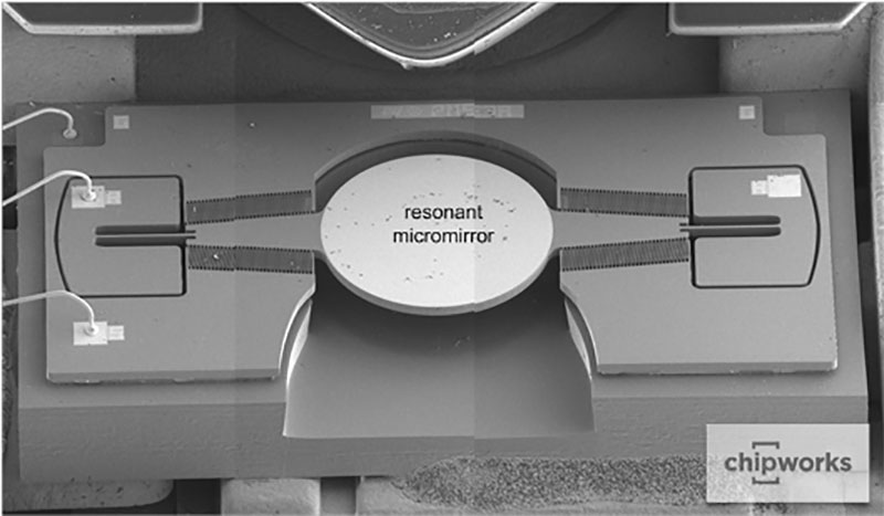
[Chipworks] has just released the details on their latest teardown on an Intel RealSense gesture camera that was built into a Lenovo laptop. Teardowns are always interesting (and we suspect that [Chipworks] can’t eat breakfast without tearing it down), but this one reveals some fascinating details on how you build a projector into a module that fits into a laptop bezel. While most structured light projectors use a single, static pattern projected through a mask, this one uses a real projection mechanism to send different patterns that help the device detect gestures faster, all in a mechanism that is thinner than a poker chip.
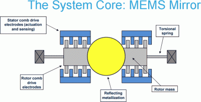
 It does this by using an impressive miniaturized projector made of three tiny components: an IR laser, a line lens and a resonant micromirror. The line lens takes the point of light from the IR laser and turns it into a flat horizontal line. This is then bounced off the resonant micromirror, which is twisted by an electrical signal. This micromirror is moved by a torsional drive system, where an electrostatic signal twists the mirror, which is manufactured in a single piece. The system is described in more detail in this PDF of a presentation by the makers, ST Micro. This combination of lens and rapidly moving mirrors creates a pattern of light that is projected, and the reflection is detected by the IR camera on the other side of the module, which is used to create a 3D model that can be used to detect gestures, faces, and other objects. It’s a neat insight into how you can miniaturize things by approaching them in a different way.


That’s a pretty awesome presentation!
Can’t wait to read the data sheets and application notes; the phase locking algorithm mentioned on the last slide really does spark my signal processing interest/meets my experience, so implementing a micromirror frontend for any signal processing hardware sounds cool; for personal reasons, using off the shelf modular SDR hardware sounds like the most attractive choice :)
I wonder if they used moving mirror to bypas some patent describing fixed pattern projection.
I went for number 2 and got some more thoughts:
We have rolling shutter IR camera and moving beam IR projector. Wouldnt this require projector to be more powerful? or synchronized in some way with projector, at least leading by few lines?
My intuition tells me ability to project different patterns every frame gives them a lot more spatial resolution ‘for free’, above the resolution of IR camera used.
hmmm, projector is analog in one dimension, in theory they could have infinite resolution in that dimension?
If they are smart (and Intel employs a lot of smart people) they could (and probably do?) dynamically generate patterns depending on last recovered depth map to concentrate on areas with biggest delta (edges) = extract most details where it counts.
edit: EETimes claims its 16 fixed patterns, a little less exciting. Plus this is their front facing low range depth camera. Back camera uses Stereo vision IR cameras plus different projector.
Rasz, yes you are right. The back camera version uses stereo and time of flight, but the module is larger and wouldn’t fit into a bezel as well.
Might a laser printer provide sufficient functionality for replicating this, sans form-factor?
if they succeed in popularizing this you will be able to pick up laptop modules for $5 on ebay just like laptop webcam modules (I currently rock macbook camera module myself, required microscope to solder tho :P)
Yes. Laser printers have a servo controlled spinning mirror to scan the beam across the drum aperture. That whine that increases pitch just before you print something is the mirror spinning up to speed. You would need another moving mirror at the output to scan the beam orthogonally. This would have to be synced to the position of the spinning mirror, either by tapping the mirror motor’s tach or using a photodiode at the edge of the beam path.
IIRC it’s a prism on a RPM closed loop motor, not a servo.
“Servo controlled” as in closed loop control, not the thing that you stick on RC models. These are usually brushless pancake motors with a Hall effect sensor as a tach for feedback. And it’s definitely not a prism but a multifaceted front surface mirror, usually polished aluminum.
I don’t get it. How are they generating 2d patterns with a line shaped beam and a single movable mirror?
Ah, I see. The example pattern photo is from a different model. From what little info there is in the article it seems it scans a line back and forth across the scene. The MEMS mirror resonates and isn’t commanded to different positions by the processor. This is very similar to some barcode scanners which use a mirror on a spring mount and a solenoid to make it oscillate, only much smaller.
I was curious like yourself on that, chango. I don’t think it uses a 1d camera approach (like supermarket scanners), but instead uses a series of vertical lines created by pulsing the laser on/off in sync with the resonant mirror: see page 12 of the presentation for an illustration. So, it is a pattern, but not quite as complex as the image in the teardown shows. That might be from the rear camera version of the RealSense, which is bigger and uses time of flight, I believe.
Neet! Is there anywhere I can get a mirror like that off the shelf? The MEMS mirrors I’ve so far cost an arm and a leg.
I think they get cheaper when you buy 1,000,000 at once. Other than that, how about tearing down a broken DLP projector?
They aren’t exactly running in a sweeping mode, more like 1-0. And 1×1 micrometer is not exactly a lot of space to work with.
It’s odd that they don’t have huge issues with vibrations, a resonant micro mirror spreading light out to a large area, you’d think it would have an error rate of 70% at least as every tiny shock to the device would throw things around.
But I guess that’s where the ‘thousands times a seconds’ comes into play?
DLP chips do not have vibration issues.
They are used in all kinds of projectors and devices.
That doesn’t answer anything about the why, but I expect it’s simply a case of the scan needing relatively coarse precision and the mirror and cam being subject to the same vibration.
.
And DLP TV’s/projectors don’t use a mirror in a resonant setup, they use a great many mirrors, that are not resonating AFAIK. And they aren’t on thugs like a not so stable table or person’s lap like a laptop. So a slightly different setup
Wonder if they will get sued by Texas Instruments…..DLP.
I would imagine TI has a patent that specifies an array, not a single pixel. Also the DLP is more designed as an output and this is more as an input. But hey, stranger things have happened and its very reasonable to expect TI might pursue this.
TI has hundreds of patents on Micromirror devices.
They have purchased other companies in the past whenever they start developing something similar.
Its not an ‘input’. its light bouncing off a micro mirror which is what DLP is.
I bet they had to design things different to avoid the TI patents, though maybe the TI patents have expired from the 1990’s
How did you come up with that 70% error rate estimate?
Purely a wild guess based on the known limits of a video camera (60HZ)) and from me trying to hold a camera by hand and getting sharp pictures at 1/60th of a second settings with some zoom in effect :)
As well as from looking through a telescope on a wooden floor, it’s hard to avoid vibration in many circumstances, at least without some electro-mechanical stabilizing system.