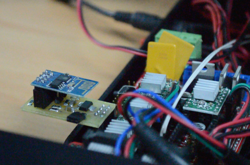
The proliferation of DIY 3D printers has been helped in large measure by the awesome open-source RepRap project. A major part of this project is the RAMPS board – a single control board / shield to which all of the other parts of the printer can be easily hooked up. A USB connection to a computer is the usual link of choice, unless the RAMPS board has the SD-Card option to allow the 3D printer to operate untethered. [Chetan Patil] from CreatorBot built a breakout board to help attach either the ESP8266 WiFi or the HC-05 Bluetooth module to the Aux-1 header on the RAMPS board. This lets him stream G-code to the printer and allow remote control and monitoring.
While the cheap ESP8266 modules are the current flavor of the season with Hackers, getting them to work can be quite a hair tearing exercise. So [Chetan] did some hacking to figure out the tool chain for developing on the ESP module and found that LUA API from NodeMcu would be a good start. The breakout board is nothing more than a few headers for the ESP8266, the HC-05 and the Aux-1 connections, with a few resistors, a switch to set boot loader mode and a 3.3V regulator. If you’re new to the ESP8266, use this quick, handy, guide by [Peter Jennings] to get started with the NodeMCU and Lualoader. [Chetan]’s code for flashing on the ESP8266, along with the Eagle board design files are available via his Github repo. Just flash the code to the ESP8266 and you’re ready to go.
One gotcha to be aware of is to plug in the ESP module after the printer has booted up. Otherwise the initial communication from the ESP module causes the printer to lock up. We are sure this is something that can be taken care of with an improved breakout board design. Maybe use a digital signal from the Arduino Mega on the RAMPS board to keep the ESP module disabled for a while during start up, perhaps? The video after the break gives a short overview of the hack.


http://www.esp8266.com has had a few people have been talking about grbl and ramps, I will have to track them down and post a link!
Very nicely done
Thank you :)
Why not use one of the GPIO to switch the TX pin after boot? A simple OR gate will do, but you can go transistor as well.
Thanks for the suggestions, for next version i thought to add this feature..
The “gotcha” at the end sounds like the serial communication might lock up the bootloader of the Arduino, which thinks it might be an attempted firmware-flash and waits indefinitely unti it’s finished.
If that’s the case, an alternative bootloader on the Arduino Mega (or no bootloader at all) might do the trick.
Had the exact same thought!
This is the firmware you want: https://github.com/beckdac/ESP8266-transparent-bridge
It is a completely transparent serial to TCP socket bridge. I have been using it with AVRs including RAMPs. You can upload hex files to the AVR easily using the stock optiboot and avrdude, e.g.
avrdude -c avrisp -p m328p -P net:192.168.4.1:23 -F -U flash:w:mySketch.hex:i
Why use Lua in the first place?
Use the Esp8266 Arduino plugin, program it in the same environments as the ramps firmware and simply flash the Esp straight from the Arduino IDE.
https://github.com/esp8266/arduino
Theres no “hair tearing” involved. Its as easy as uploading a sketch to an arduino board.
And you can use many of the existing arduino libraries that just work or Esp specific libraries that have been ported over.
Good job
I’ve been testing this as well and have run into a couple problems.
1. The extra latency causes slowing down and stuttering during sequences of many short consecutive moves (curves).
2. Dropped connections.
Maybe that can be solved by implementing a buffer for the next n G-codes? I don’t know the ramps board, but if it has an SPI port exposed one could even buffer the whole job on an spi-flash or on (micro)-SD.
Why not use the ESP for loading a stl file to the sd card in the printer and then use it to start/stop/resume the printer? It could even serve a web page to which you can upload the stl file, control status and have a browser notification when it finishes.
Would this shield I’ve cooked work?
Sorry, I’ve been trying to se github but I’ve been unable to upload my modified files, so here they are:
https://dl.dropboxusercontent.com/u/6334877/ESP_RAMPS.sch
https://dl.dropboxusercontent.com/u/6334877/ESP_RAMPS.brd
I’ve added values, I’ve changed the fixed voltage regulator for an adjustable one, and a Mosfet Channel N Enhancement Mode TO-92-3L to switch the ES_TX through GPIO2 (and also a thermistor shield).
Thanks in advance
Would have liked to see these files. Eagle didn’t recognize them.
Couldn’t I just use the 3.3v line from the Arduino itself? (I dont have a 3.3v regulator on hand ;))
Great source!
I’m sorry to bump this thread I’m trying to do the same thing. However, i want to use octoprint in normal running of my printer and repetier host on my laptop for calibrating the printer etc more easily. is there a way to add the wifi module and still have the ramps tethered via usb to octoprint and the pi? or do you know of a way now to control octoprint via repetier host using the same usb connection to the pi but connecting over wifi to a laptop?