Motorized Camera Mount Was Once A 3D Printer

If you plan on building your own motorized camera mount, a 3D printer can definitely be of help. But in this case, [dslrdiy] didn’t use it for printing out parts — finding himself with little use for an old printer built from scrap back in the day, he decided to repurpose it and turn it into a remote controlled DSLR camera mount that’s capable of panning, tilting, and sliding.

The main goal was to not only salvage the stepper motors and controller board, in this case an Arduino Mega 2560 with RAMPS board, but also to keep the original firmware itself in use. For this to work, [dslrdiy] redesigned the mechanical parts that would allow him to perform the different camera movements using regular G-Code instructions operating the X, Y, and Z axes to pan, tilt, and slide respectively.

The G-Code instructions themselves are sent via UART by an accompanying control box housing an ESP32. This allows the camera mount to operated by either via joystick and buttons, or via serial Bluetooth connection, for example from a phone. The ESP32 system also allows to set predefined positions to move to, along with speed and other motor tweaks. You can see it all demonstrated in the video after the break.

While there’s simpler solutions for camera mounts out there, this is certainly an interesting approach. It also shows just how far desktop 3D printers have come if we already find the older generations repurposed like this. For more of [dslrdiy]’s work with 3D printers and cameras, check out his customizable lens caps.

Continue reading “Motorized Camera Mount Was Once A 3D Printer”

Giant CNC Machine Measures A Full Cubic Meter

There are plenty of designs for table-top 3D printers, engravers, and general CNC machines out there. However, if you wanna build big things and build them fast, sometimes you need a machine that can handle bigger jobs. This gigantic 1x1x1 m 5-axis CNC machine from [Brian Brocken] absolutely fits the bill.

The build relies on 3D-printed components and aluminium tubing to make it accessible for anyone to put together. [Brian] notes that 25×25 mm tubing with a 2 mm wall thickness does an okay job, but those aiming to minimize deflection would do well to upgrade to 5 mm thickness instead. Stepper motors are NEMA 23 size, though the Y-axis uses a pair of NEMA 17s. This is necessary to deal with the immense size of the machine. Control is thanks to an Arduino Mega fitted with a RAMPS board, running the Marlin firmware.

The plan is to use the machine to test out a variety of CNC machining techniques. It could make for a great maxi-sized 3D printer, and should be able to handle some basic 5-axis milling of very soft materials like foams. This might seem silly on the face of it, but it can be of great use for mold making tasks.

We’ve seen giant CNC routers built before, too, and they can readily be put to great use. Video after the break.

Continue reading “Giant CNC Machine Measures A Full Cubic Meter”

RAMPS Rebuild Keeps Robox 3D Printer Out Of Junk Bin

A 3D printer is a wonderful invention, but it needs maintenance like every machine that runs for long hours. [Rob Ward] had a well-used Robox 3D printer that was in need of some repairs, but getting the necessary replacement parts shipped to Australia was cost-prohibitive. Rather than see a beloved printer be scrapped as e-waste, he decided to rebuild it using components that he could more easily source. Unfortunately the proprietary software and design of the Robox made this a bit difficult, so it was decided a brain transplant was the best path forward.

Step one was to deduce how the motors worked. A spare RAMPS 1.4 board and Arduino Mega2560 made short work of the limit switches and XYZ motors. This was largely accomplished by splicing into the PCBs themselves. The Bowden filament driver motor had a filament detector and an optical travel sensor that required a bit of extra tuning, but now the challenging task was next: extruding.

The printer’s new custom hotend.

With a cheap CR10 hot end from an online auction house, [Rob] began modifying the filament feed to feed in a different direction than the Robox was designed for (the filament comes in at a 90-degree angle on the stock Robox). A fan was needed to cool the filament feed line. Initial results were mixed with lots of blockages and clogs in the filament. A better hot end and a machined aluminum bracket for a smoother path made more reliable prints.

The original bed heater was an excellent heater but it was a 240 VAC heater. Reluctant to having high voltages running through his hacked system, he switched them out for 12 VDC adhesive pads. A MOSFET and MOSFET buffer allowed the bed to reach a temperature workable for PLA. [Rob] upgraded to a GT2560 running Marlin 2.x.x.

With a reliable machine, [Rob] stepped back to admire his work. However, the conversion to the feed being perpendicular to the bed surface had reduced his overall build height. With some modeling in OpenSCAD and some clever use of a standard silicone sock, he had a solution that fed the wire into the back of the hot end, allowing to reclaim some of the build height.

It was a long twelves months of work but the write-up is a joy to read. He’s included STL and SCAD files for the replacement parts on the printer. If you’re interested in seeing more machines rebuilt, why not take a look at this knitting machine gifted with a new brain.

The 3D Printed Plotter You Didn’t Know You Needed

We’ve been seeing an influx of repurposed 3D printers recently. Thrifty hackers have been leveraging cheap 3D printers as a way to bootstrap their builds, on everything from laser engravers to pick and place machines. There’s nothing wrong with that, and honestly when you can get a cheap 3D printer for less than the cost of the components separately thanks to the economies of scale, you’d be foolish not to.

But there’s still something to be said for the classic RepRap mentality of building things using printed parts and smooth rods. Case in point, the largely 3D printed plotter that [darth vader] sent in for our viewing pleasure. This isn’t somebody sicking a pen on the extruder of their open box Monoprice special, this is a purpose built plotter and it shows. In the video after the break you can see not only how well it draws, but also how large of a work area it has compared to a modified 3D printer.

If you know your way around a 3D printer, most of it should look pretty familiar to you. Using the same GT2 belts, steppers, end stop switches, and linear bearings which are ubiquitous in 3D printers, it shouldn’t be difficult to source the parts to build your own. It even uses a Mega 2560 with RAMPS 1.4 running Marlin 1.1.9 for control.

The biggest difference is the physical layout. Since there’s no heavy hotend or extruder assembly to move around, the plotter has a cantilever design which gives it far greater reach. As it only needs to sightly lift the pen off the paper, there’s no need for a complex Z axis with leadscrews either; a simple servo mounted to the end of the arm is used to raise and lift the pen. We especially like the use of a tape measure as strain relief for his wiring, a fantastic tip that we (and many of you) fell in love with last year.

While it’s hard to beat just tossing a pen onto the business end of your desktop 3D printer in terms of convenience, we think it’s pretty clear from this build that the results don’t quite compare. If you want a real plotter, build a real plotter.

Continue reading “The 3D Printed Plotter You Didn’t Know You Needed”

Maker Faire NY: Cocoa Press Chocolate Printer

If you haven’t figured it out by now, the hype over desktop filament printers is pretty much over. But that doesn’t mean there aren’t new avenues worth exploring that use the basic FDM printer technology. If anything, the low cost and high availability of 3D printer parts and kits makes it easier to branch off into new territory. For example, experimenting with other materials which lend themselves to being “printed” layer by layer like a thermoplastic. Materials such as cement, clay, or even chocolate.

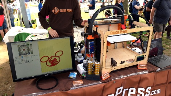
[Ellie Weinstein] brought her Cocoa Press printer to the 2018 World Maker Faire in New York, and we have to say it’s a pretty impressive piece of engineering. Hackers have been known to throw a syringe-based paste extruder onto a regular 3D printer and try their luck with squirting out an edible object from time to time, but the Cocoa Press is truly a purpose built culinary machine.

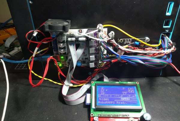
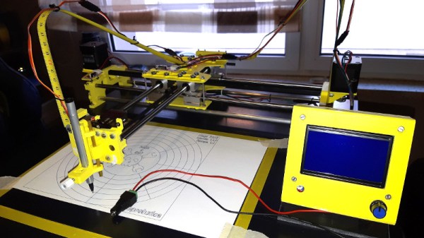
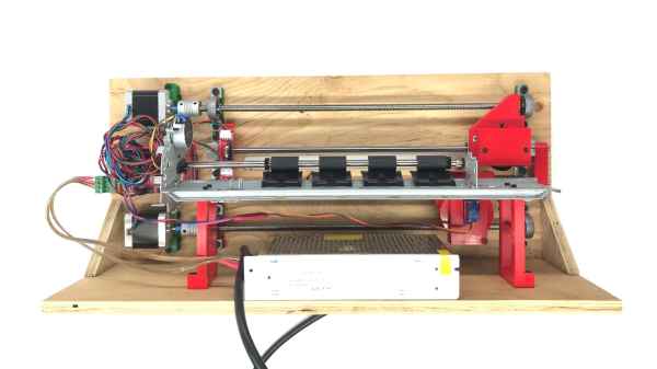
Outwardly it features the plywood case and vaguely Makerbot-looking layout that we’ve seen plenty of times before in DIY 3D printers. It even uses the same RAMPS controller running Marlin that powers your average homebrew printer. But beyond these surface similarities, the Cocoa Press has a number of purpose-built components that make it uniquely qualified to handle the challenges of building with molten chocolate.

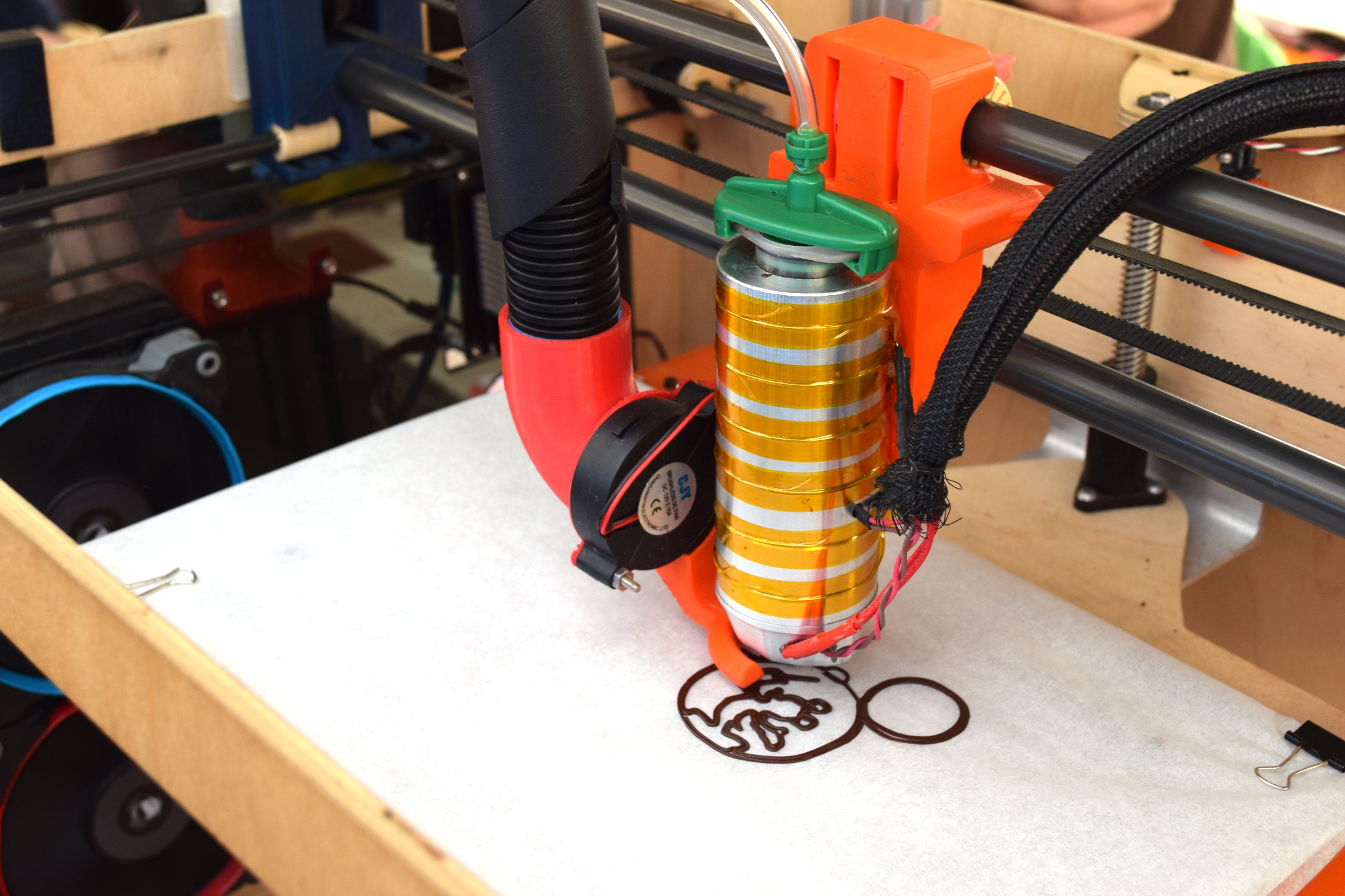
For one, beyond the nozzle and the walls of the syringe, nothing physically comes into contact with the chocolate to be printed; keeping the mess and chance of contamination to a minimum. The leadscrew actuated plunger used in common paste extruders is removed in favor of a purely air powered system: a compressor pumps up a small reservoir tank with filtered and dried air, and the Marlin commands which would normally rotate the extruder stepper motor are intercepted and used to trigger an air valve. These bursts of pressurized air fill the empty area above the chocolate and force it out of the 0.8 mm nozzle.

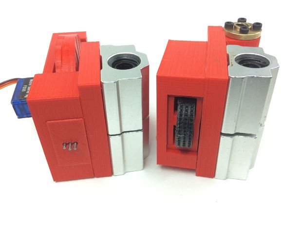
In a normal 3D printer, the “melt zone” is tiny, which allows for the heater itself to be relatively small. But that won’t work here; the entire chocolate load has to be liquefied. It’s a bit like having to keep a whole roll of PLA melted during the entire print. Accordingly, the heater on the Cocoa Press is huge, and [Ellie] even had a couple spare heaters loaded up with chocolate syringes next to the printer to keep them warm until they’re ready to get loaded up.

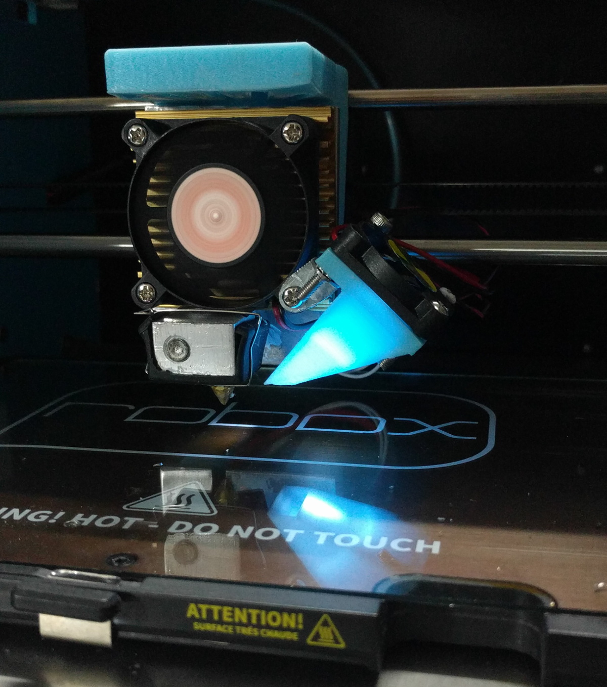
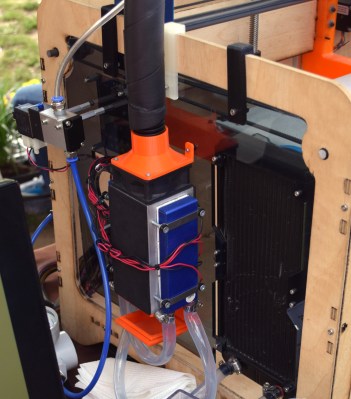
Of course, getting your working material hot in a 3D printer is only half the battle, you also need to rapidly cool it back down if you want it to hold its shape as new layers are placed on top of it. A normal 3D printer can generally get away with a little fan hanging next to the nozzle, but [Ellie] found the chocolate needed a bit of a chill to really solidify.

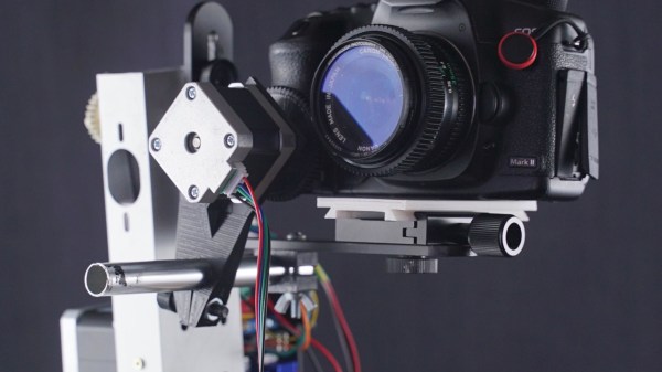
So she came up with a cooling system that makes use of water-cooled Peltier units. The cold side of the Peltier array is inside a box through which air is forced, which makes its way through an insulated hose up to the extruder, where a centrifugal fan and 3D printed manifold direct it towards the just-printed chocolate. She reports this system works well under normal circumstances, but unusually high ambient temperatures can overwhelm the cooler.

While “the man” prevented show goers from actually eating any of the machine’s creations (to give out food in New York, you must first register with the city), they certainly looked fantastic, and we’re interested in seeing where the project goes from here.

Wood Shines In This SCARA Robotic Arm Project

[igarrido] has shared a project that’s been in the works for a long time now; a wooden desktop robotic arm, named Virk I. The wood is Australian Blackwood and looks gorgeous. [igarrido] is clear that it is a side project, but has decided to try producing a small run of eight units to try to gauge interest in the design. He has been busy cutting the parts and assembling in his spare time.

Besides the beautifully finished wood, some of the interesting elements include hollow rotary joints, which mean less cable clutter and a much tidier assembly. 3D printer drivers are a common go-to for CNC designs, and the Virk I is no different. The prototype is driven by a RAMPS 1.4 board, but [igarrido] explains that while this does the job for moving the joints, it’s not ideal. To be truly useful, a driver would need to have SCARA kinematic support, which he says that to his knowledge is something no open source 3D printer driver offers. Without such a driver, the software has no concept of how the joints physically relate to one another, which is needed to make unified and coherent movements. As a result, users must control motors and joints individually, instead of being able to direct the arm as a whole to move to specific coordinates. Still, Virk I might be what’s needed to get that development going. A video of some test movements is embedded below, showing how everything works so far.

Continue reading “Wood Shines In This SCARA Robotic Arm Project”

OpenBraille Is An Impressive DIY Embosser

In 2024, the Braille system will have been around for 200 years. What better way to mark the occasion than with an open source project devoted to making embossing equipment affordable for the visually impaired? This long overdue cause became the plight of [ccampos7], who couldn’t find a DIY embosser kit and set out to build one himself.

While other embossers forcibly punch the letters in one go, OpenBraille takes a more gradual approach to ensure a clean impression with a rolling motion. Paper is placed between a mechanical encoder with moving pins and a dimpled roller that provides resistance and a place to land. The embossing head is driven by an Arduino Mega and a standard RAMPS board, as the rest of the system relies on Cartesian movement.

The encoder and roller.

The encoder mechanism itself is pretty interesting. A micro servo drives a 3D printed wheel with three distinct tracks around half of the edge. The peaks and valleys encoded in these plastic tracks actuate the embossing pins, which are made from nails embedded through the sides of hex nuts. There’s a quick demo of the encoder movement after the break, and another video of it in action on the OpenBraille Facebook page.

[ccampos7] has all the files up on Thingiverse and plans to post the software soon. You should also check out this compact embosser that was recognized in the first round of the 2017 Hackaday Prize which is a nice all-print Braille concept. Continue reading “OpenBraille Is An Impressive DIY Embosser”