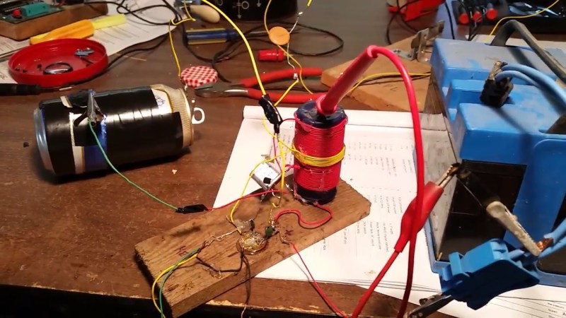
If you’re getting started building your own ham radio gear, it’s hard to imagine a more low-tech transmitter than the Mighty Mite, but [Paul Hodges, KA5WPL] took it one step further and rolled his own variable capacitor. (That’s the beer can with tape and alligator clips that you see on the left.)
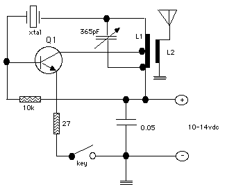
A Mighty Mite is barely a radio at all. One transistor, capacitor, crystal and inductor in the form of a bunch of wire wrapped around a pill bottle form a minimalist oscillator, and then by keying this on and off with a switch, you’re sending Morse code. [Bill Meara], of the Soldersmoke Podcast, has been a passionate advocate of the Mighty Mite, suggesting that it can be made by scrounging the 3.57954 MHz colorburst crystal from an old analog TV set, which tunes the radio to a legal frequency for ham radio operators. (It will also probably work with other low-MHz crystals from your junkbox, but it won’t necessarily be legal.)
 If the crystal is “easily” scavengeable, and the rest of the radio is easily home-made, the tuning capacitor (obtainable from old AM/FM radios) can become the sticking point. So [Paul] cut up two aluminum “beverage” cans, wrapped the inner one in electrical tape, hooked up wires and made his own variable capacitor. By sliding the cans in or out so that more or less of them overlap, he can tune the radio to exactly the crystal’s natural frequency.
If you’re interested in building a Mighty Mite, you should definitely look at the topic on Soldersmoke. There are more build instructions online as well as plans for an optional filter to take off the harmonics if you’re feeling ambitious.
If you’re not a Morse code wiz, we can’t help but note that you could replace the key with a simple FET (we’d use a 2N7000, but whatever) and then you’ve got the radio under microcontroller control. Scavenge through Hackaday’s recent Morse code projects for ideas, and we’re sure you’ll come up with something good.


This. This is what lets me make a transmitter and reciever for the spawnling; the variable capacitor has always been a sticking point
Agreed. Heck, even the colorburst crystal can be tough to find these days. I’ve been scrounging crystals for years and I only have 4 of them.
This is just the excuse I need to pick up a 12-pack of my favorite Polar Orange Dry soda the next time I go shopping.
Colorburst crystal are plentiful on ebay. I bought 10 a few months ago for $1.50 so I could try building a crystal ladder filter.
The surplus houses usually have colorburst crystals on the cheap as well. I know I got a couple from grab-bag type deals.
Works better with Moxie cans…
Why? Ebay works in Australia. I’m sure you’d find other sources on Google too. The GQRP club out of the UK sells polyvaricons and crystals to people all over the world. Of course.. just about any old transistor radio that tunes the AM broadcast band has one.
http://bfy.tw/22cL
I’m constantly reading this cry on the internet that variable capacitors are somehow hard to come by. And yet.. on that same internet I have absolutly no problem finding them! Not only that but here in the US I see them going cheap at hamfests all the time. Not just those little polyvaricons mind you but big ones! They used to be expensive. For a while after the prices went down I snapped up every one I saw b/c I though it was a fluke. Now I have a junkbox full and still find them available!
Any diode or transistor may be used as a https://en.wikipedia.org/wiki/Varicap. You need a very clean DC source for tuning this circuit because otherwise you are frequency modulating your signal, but fortunately with for example MOSFETs you have very little leak current so you can use a battery to power it.
High-amperage, low voltage devices give the highest capacitance. These suffice for all but the longest wavelengths.
I would very much like to see an experienced radio hacker implement this with the regen circuit… Could be a big hit!
Uh, if you really are located in Australia, go to Jaycars – they have variable caps in stock! I bought one just last weekend too! :S
This is a transmit-only device. I suspect a receiver would be at least slightly more difficult to produce, but I’m not familiar with these old-school designs. Pretty neat!
Wouldn’t an old fashioned Foxhole crystal radio receiver work?
Yes and no, crystal radios only receive AM signals (and a tiny bit of FM if you use slope detection). With one exception: with a chopper/interrupter, you can turn the silent DC signal (from detection of an unmodulated Continuous Wave signal) into a audible tone. That can be done with a mechanical interruptor working on clockwork.
If you would modulate the transmitter signal, you’d be able to use a crystal radio. If you want to go fully retro, you can just insert a carbon microphone into the base of the transistor. You end up with a weird mixture between AM and FM, but it will be somewhat intelligable.
An oscillating regenerative receiver capable of receiving CW signals can also be built with a minimum of components. Take a look at this: http://b-kainka.de/bastel107.htm
A little creative switching could use your high powered oscillator as the osc in a ne602/sa612/etc dc (Direct Conversion) rx.. something ala http://www.qsl.net/yo5ofh/projects/80m_rx_ne602/80m_mini.htm ..
A regenerative receiver can receive CW if it’s adjusted to oscillate and isn’t much more complex than this transmitter. You’d probably follow the actual regen detector with an audio amp or two. I used to get surprisingly good reception with Radio Shack’s sadly defunct P-Box shortwave receiver kit, which was IIRC 3 transistors.
WARNING:
Whatever you do, Don’t build this and take it to school
Or just let people know about it before you bring it to school. Getting permission beforehand kinda short-circuits the “bring in the bomb squad” reflex.
Hi. Does anybody know what is the range of this setup in open air (thinking about baloon transmitter)?
Somewhere I remember seeing someone had an html table with contacts listed that they had made with one with distances up into the tripple digits as measured in km. I wish I could remember where. It was likely something that I saw linked to from the Soldersmoke blog but it was years ago.
That being said.. I think most people build it for the simplicity just as a beginner’s tool.. verify that it does work.. never makes a contact and moves on to some slightly more advanced project.
This circuit may not be a good fit for a balloon. First, it’s got more power than necessary (on a 9V battery), but it also wants a really long antenna as well, which adds weight.
Most (?) balloons use 144 MHz to work with the APRS network. No matter what radio rig you have, someone with a permanent ground station has a better one, and if they report APRS messages, they’ll post its location to the net for you.
If you look around (I think I wrote up a very-low-power balloon transmitter recently) you’ll find a more appropriate radio solution.
The MMM is a neat little one transistor transmitter project. But.. you can find a bunch of similar transmitters, receivers and even one transistor transcievers at AA1TJ’s old website. https://web.archive.org/web/20110619022239/http://aa1tj.com/radio.html
In other words.. if you like this you will love that!
Great resource!
My quick look through those circuits makes me think that they’d be great second (third, fourth … seventyth) projects after people have gotten this circuit up and running.
From the video “…I have oscillations…”
Well this may help, http://tatica.org/en/2014/08/18/estabilizar-videos-en-linux-con-transcode-y-vid-stab/
Article had me checking if the source of new 365 pd tuning caps still have them still have them. They are still listed on their webpage. I need to buy a couple.
I seem to remember see some very interesting transmitters using both voltage regulators and 8-pin inverter IC’s, even some with simple VFO tank circuits (no XTALs) out of the Philippians and India (some were even housed in foil covered match boxes). Probably not up to FCC regs, but fun . . . One very similar one actually used a PCB the size of a standard Post QSL card that had the spiral “coils” etched out on the back side and only needed a FET, a resistor and a few caps to make a 40m QRP transmitter.