High speed photography is fun. Ultra high frame rate video, even more so. But since not many of us have access to $10,000 HFR cameras… we have to make do with long exposure shots a perfectly timed camera flash. You can design a system to trigger the flash at just the right millisecond — but they’re still pretty expensive typically.
[Electronupdate] has a 100W LED module and penchant for Arduino Nanos — so he wondered if he could make an affordable high speed camera rig — and he did.
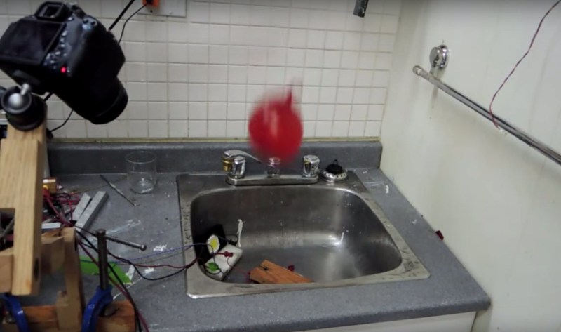
It’s a pretty slick little setup. He has a limit switch mounted to a nail on a piece of wood — when the water balloon drops on it, it triggers the mechanical switch. The Arduino then triggers the LED flash, which is quite a large load and requires a High Side Switch to operate. A small LCD and series of buttons allow him to dial in the time offset just right in order to get some awesome photos of a water balloon exploding.
Alternatively, you can achieve the same effect with friggin’ lasers.


With short enough pulses, there’s no need to restrict yourself to the LED’s rated current, either; it simply doesn’t have time to heat up and damage itself. I did some exploratory work for someone building ultra-high-speed flashes; we were able to overdrive high power LEDs by a factor of 20 for durations less than 5 microseconds. That worked out to putting out a peak energy of about 32 kilowatts into an array of 9 high power LEDs.
Correction: I looked it up, and it was closer to 15 kilowatts.
Groovy! Is there a decreasing relationship between power and light output? There’s only so many electrons something something energy levels mumble. Only so many LED molecules to illuminate. Impressive though.
Yup, it’s a definite case of diminishing returns. At 20 times rated current, the light output is only about 10x, for 50% baseline efficiency.
But how does the actual light output scale with input power?
That would be interesting to know. Increasing LED current always results in diminished returns, so I would expect output to have maxed out well below 15kW.
As near as I’ve been able to tell, LED luminous flux is basically proportionate to current, period. The inefficiency happens as the forward voltage goes up.
At 20x rated output, the efficiency was about 50% of baseline.
Using an interrupt would have helped the timing on this a lot.
Actually not. If he arms the circuit and all it is doing is polling the port in a loop, the timing will be a lot more deterministic. Interrupt handler call is not instantaneous, there is some overhead to it. Not something you would want if you need to do precise timing on a relatively slow micro in software.
The AVR series interrupts suck, IIRC buried somewhere within the manual it states something along the lines that each interrupt can take 1 or 2 cycles to respond ( might be higher, I forget). Not withstanding anything that gets pushed to the stack. It’s one of the reasons I avoid the Arduino platform and don’t always use C since I can write much more responsive code if I know I don’t always need to push all 16 or 33 registers to the stack. In addition, tricks like using one of the spare timers to keep your code in lockstep is just ridiculus.
I hear the PIC has more consistent interrupt timings but I haven’t yet had the need to go that route. I just switch to old school polling and start cycle counting if my timings are that tight. A throwback from racing the beam I guess.
I knew my memory on the ISR was a bit rusty. It’s actually more like 5 clock cycles. See below….
2 cycle latency for handling an interrupt is hardly pathetic. I’m not sure what interrupt latency actually is on the AVR but I would be surprised if it was just 2 clocks, the processor has to push both bytes of the program counter then do a jump, probably 4-5 clocks minimum.
You can program in C with the AVR (even arduino) and just do the ISR in assembler. If you are just setting a GPIO bit and changing a variable flag you can do this without saving any registers making the overhead of the ISR minimal. This also means you have to write very little assembler and can keep most of your code in C.\
Assuming the interrupt latency is 5 clocks (which sounds about right), that is about 0.3us (@16mhz). If you write the code without using interrupts, you would use a loop that waits for an external event and sets a GPIO pin. Assuming you write this with a timeout (instead of a true infinite loop), the worst case latency would be about 11 clocks (dec/brne/dec/brne/rjmp/sbrc/rjmp, worst case is the pin transition happens just after the last sbrc, and assumes you are using a 16 bit timeout counter [which might not be long enough at this speed]).
If you are looking at latencies in this range (5-11 clocks), the delay is pretty insignificant for doing this type of photography. Whether you are photographing something being hit by a bullet, a balloon popping, water drops or anything else that involves physical movement on a non-tiny scale repeatability counts a lot more than fast response. The optical or audio sensor used to trigger the flash is usually located in such a way to create a few _milli_seconds of delay to allow the projectile/event/etc to unfold to a state that is visually interesting. Having done a fair amount of this type of photography, I don’t think I have ever used a delay under 1ms between the trigger event and firing the flash. Given those kinds of delays, doing the delays in software in arduino is plenty fast enough as long as you are smart about structuring the code.
If you want fast, deterministic timing, use an XMEGA and the event processing hardware to do the whole thing in hardware. You can wait for a GPIO edge, start a timer, then set a GPIO pin on expiration of a timer without running a single instruction on the processor. With the E series (I think), you also have some minimal programmable gate array fabric to do more complex things (like have an enable input to arm things).
The 8 bit PICs can have lower latency because they have a hardware 16 level stack instead of the traditional ram based stack used in the AVR and almost all other processors. The consequences of this 16 level hardware stack mean that by default, local variables in C are not allocated on the stack but are implicitly static so you cannot call a function with locals re-entrantly without getting bizarre bugs because the local variables are the same memory locations are the outer invocation. Combine this with the absolute pain in the rear associated with coding the assembler on the PIC8/16 processors and dealing with the wacky RAM pages that are combined with IO ports and the code associated with page registers and after going one contract writing a set of PIC8/16 applications (mixed C and assembler), I will never do another PIC8/16 project for any amount of money. Microchip doesn’t provide bootloaders for a lot of the processors and different members of the PIC family have radically different internal hardware (EEROM vs Flash, programmable vs fixed pin mapping, etc etc) making porting the bootloader to different members of the family a PITA. I would also characterize the quality of the free tools for the PIC8/16 processors as being extremely poor compared to the AVR tools.
The PIC 18/24/32 processors are completely different architectures and while my experience with them is minimal, they appear to be “real” processors which is not how I would characterize the PIC8/16 family.
Perhaps someone should let Microchip know they should apparently remove the PIC18 family from their “8-bit MCU” section – they seem to think that’s what those are. The fools! Also, while they seem to have got the N-level deep hardware stack for the program counter correctly, they should really stop wasetfully allocating about 256 bytes (or one RAM page) in just about every linker file they have for PIC18 MCU for some imaginary “stack” where they seem to think variables get passed on function calls. They clearly have no clue what they’re talking about.
Dean,
Any examples of the photos you took or hardware used?
This is a water drop hitting the back of a plastic dixie plate with a canon speedlight 430ex set on minimum power. You can see the limits of what you can freeze with a standard flash, as well as the plate resonance from the drop impact being transmitted up the crown.
http://imgur.com/gallery/ZBLBfTT/new
This was an experiment in taking multiple frames gradually increasing the delay between drop detection and flash trigger and then stitching the frames together into an animation that showed the formation and collapse of the crown.
This was a project done with out intern for a class project of hers and was done in Arduino with a busy-wait loop to detect the drop (laser pointed at the phototransistor from a opto-interrupter, running to a GPIO using a pullup resistor), delayus to wait to trigger the flash (delays from 1ms to around 10ms) and a digitalWrite to trigger the flash (through a phototransistor opto-isolator).
I have tried building an LED based high speed flash to generate 1-2us flash durations at 100khz to freeze insect wings while being filmed by a 100Kframe/sec high speed camera. My experience was that it was just barely possible to get LEDs switched on and off in this time frame, but the CRI from phosphor based leds is all over the place and varies widely by pulse duration. I would take claims of <1us flash duration from a white light LED with a grain of salt until you see a trace from a fast photodiode showing you exactly what the light pulse looks like.
Challenges include:
1. Using a high current, low resistance gate driver to overcome the gate charge for the relatively large mosfet you need to keep the DS inductance (mostly package) and Rdson to a minimum and overcome the miller effect (parasitic cap that couples the drain back to the gate frustrating fast turnon and turnoff).
2. Carefully choosing your mosfet
3. Using a VERY low ESR storage cap (or more likely cap array) for energy storage to dump into the LED
4. Careful layout and wiring to minimize stray inductance in the discharge path.
5. The effects of junction capacitance in the LED array (big white leds are an array, not a single junction). Diodes have a junction capacitance and parallel arrays of high current diodes can have a significant junction capacitance that gets in the way of fast edges.
6. It takes a LOT of light at 1us pulse duration, if are are going for a 1J discharge (very modest), you need 1 million watts of instantaneous power into the diode to get to 1J in 1us. If you are using a 36V led, that translates to nearly 30,000A discharge current, and assuming a minimum rise and fall time of 1us, that means that your dI/dT is 3×10^10 (which is huge)
Getting <1us pulses from an air gap flash is not difficult, but charging one fast enough for 100khz flash repetition is a challenge (with a 1J discharge you are talking 100kW power in assuming everything is 100% efficient). In reality this can't be sustained for any significant fraction of a second without serious investment, but fortunately this application only needed a couple of hundred pulses in a run.
“My experience was that it was just barely possible to get LEDs switched on and off in this time frame, but the CRI from phosphor based leds is all over the place and varies widely by pulse duration.”
Really? We didn’t have that issue at all; they were very deterministic.
“I would take claims of <1us flash duration from a white light LED with a grain of salt until you see a trace from a fast photodiode showing you exactly what the light pulse looks like."
Well, here's a 3uS pulse: http://imgur.com/5s5vDu2
All of the things you list as challenges were indeed challenges, but none of them intractable. Your estimate of 1J energy for a single 1uS flash is on the high side – we were dealing with less than a tenth of that, so it's a bit dim if you really want a 1uS exposure. People compensate with longer exposures (5uS is still very fast!), multiple flash units, or sensitive cameras.
The end result – vela.io – was pretty cool, though.
Given your product design (which I think is probably a good product), a 3us pulse with 100mJ of energy spread across 9 leds yields a pulse current of 96 amps per led. This is very doable. My comments were addressed to the idea of trying to drive a single LED with enough energy to use it as a high speed flash.
But, with the array of LEDS there is a catch. A typical high end hotshoe flash generates about a 1J discharge at 1/64 power. My experience is that this is about right when the light source is 20-30cm or so from the subject and the flash is set to the longest zoom setting which for my flash is about a 50 degree light cone. You are at 1/10 this light output, so if you are shooting at a reasonably low ASA setting (200 ish for low noise digital) and have a lens at f/16 for depth of field, you are going to have to have the flash pretty close to the subject to get a correct exposure and with such a wide transmission array (the 9 LEDS), things are not inverse square at very close distances. For small subjects you might be able to get a significantly higher luminous intensity using lenses in front of the LEDs instead of reflectors around them. This would significantly narrow the illumination cone.
You can check on the CRI weirdness by using three fast photodiodes behind RGB filters (I used an RGB beam splitter from a 3 LED projector because I had one on hand [Goldmine Electronics, they may still have them]) and use a 3 channel oscilloscope to watch the color content of light pulse over the duration of the pulse. The weirdness I observed happened at the rising edge where the current had not reached its peak value. This was 2-3 years ago and high power LED construction has changed a bit since then and it is possible that the phosphors have improved.
BTW, it would be really interesting to build a version of your device with a single emitter and optics to couple the light source to a microscope. This could be a nice, inexpensive way to image fast biological processes at microscopic scale.
Air gap flashes are extremely dangerous, but with an ultra-low ESR discharge cap, very low inductance conductors between the cap and the discharge area and a well designed discharge area, you can get down to 0.1us with 10J pulses.
An array of stacked plate capacitors with a good high voltage dielectric arranged radially around a discharge tube with big bus bars carrying the pulse from the caps to the discharge tube can generate really fast pulses of light at reasonable intensities. This can be built fairly inexpensively, but 10J at 100kV is more that a little dangerous, particularly when the device can deliver 1000A pulses. I think anyone with sufficient experience to build something like this safely can take the necessary hints above. This should not be a first high voltage project for anyone.
One other technique I have always wanted to try it to use a nitrogen laser to drive a phosphor target. There is an old design for a nitrogen laser published by SciAm that produces 5-10ns light pulses at reasonable intensities (nothing like an airgap flash though). The output is UV (337nm) and the unique properties of the nitrogen laser mean you don’t need a mirror cavity and the pulse is self extinguishing so you just need a relatively easy to build pulse capacitor and discharge arrangement. In order to use it, you would need to increase the gap in the discharge spark gap and use a HV trigger pulse to initiate the discharge (same as an air gap flash). The phosphor target could be immediately underneath a sample in a microscope (use a digital camera on the microscope if you value your eyes) keeping the high voltage well away from the sample area.
“You can check on the CRI weirdness by using three fast photodiodes behind RGB filters”
Ah, now I follow. We didn’t measure each wavelength separately, no. When you say weirdness, do you mean that the spectrum shifts during the flash? Surely with the camera integrating the result, that’s not a big deal?
“BTW, it would be really interesting to build a version of your device with a single emitter and optics to couple the light source to a microscope.”
Not my device, sadly – I just designed an initial board to test the concept. What you describe is pretty close to what the people in the paper I linked did though, I think.
The change in the CRI/spectrum of the light would probably not be an issue at 3us. At 100ns to 500ns it was a pretty big issue as the ramp of the light output (and apparently the spectrum shift) was on the order of 200ns in my test setup (multiple film caps, driver and mosfet on one side of the board, led on the other with copper straps wrapped over the edges of the board carrying the discharge current). A lot of progress has been made with mosfets in the last couple of years now, so it would probably be possible to get the output rise time to under 50ns without getting too exotic.
Having the output spectrum change during the pulse can be an issue for very fast moving subjects as it will create color fringes at the start and/or end of the blur trail.
BTW, shield carefully, you should be surprised what the radiated EMI pulse from devices like this looks like and the FCC doesn’t appreciate products acting as high-power broadband transmitters even if the pulses are short.
Max: sorry about the ambiguity, if you read the last paragraph:
The PIC 18/24/32 processors are completely different architectures and while my experience with them is minimal, they appear to be “real” processors which is not how I would characterize the PIC8/16 family.
You will see that I was not trying to tar the PIC18 with the same distaste I have for the PIC8/16. I have never used a PIC18, but I have had good experiences with eh PIC32 family (albeit not with the MPLAB microchip tools).
Super! thanks for the info!
Also, this original paper demonstrating some real-world results applying the overdriving technique in order to generate bright flashes for flow velocimetry is interesting: http://elib.dlr.de/64324/1/mst075402_ledpiv_willert_2010.pdf
Seeing the scope of the instruction set of such MCU I really can’t imagine the compiler of C making it that much more complex and lengthy than straight assembler code.
It requires a couple of clock cycles for an external asychronous signal to be properly synchronized to the processor clock to avoid metastability. The only thing one can do to lower the latency is use a much faster clock speed. Or this is a case of using analog timer chips.
On my experiments with a laser measure by an LDR and voltage divider, it’s easier to set a trigger threshold and just keep polling the analog value. In practice, you end up adding delay, or moving the trigger or camera around to get the timing right.
Would a comparator be better suited than an adc (generally) for this sort of application?
The voltage divider is acting as a comparator as it is a fixed resistance. It also allows for a pot in series in order to “tune” the LDR for ambient light levels. For a high-speed photography trigger mechanism this isn’t as big of a deal since things will be dark until the flash fires,but it can also be adapted for other uses (hence the inline pot for tuning).
… LDRs are not known for their speed ;-)
Use a photodiode or phototransistor instead.
Sometimes your build with what is handy at the moment :-) Haven’t had the LDR be too slow yet as a laser trigger. A photodiode or phototransistor would probably be a more appropriate trigger mechanism though.
Jan is only half right. The tightest polling loop possible on an AVR is sbis rjmp. That means a delay of 2-5 cycles from the pin changing state.
For an ISR, the latency will be a bit more, but if the AVR is put into sleep mode while waiting for the ISR, the latency will be consistent to within a single cycle.
This is an excerpt from the 32U4 series. doc7766:
The interrupt execution response for all the enabled AVR interrupts is five clock cycles minimum.
After five clock cycles the program vector address for the actual interrupt handling routine is executed.
During these five clock cycle period, the Program Counter is pushed onto the Stack. The
vector is normally a jump to the interrupt routine, and this jump takes three clock cycles. If an
interrupt occurs during execution of a multi-cycle instruction, this instruction is completed before
the interrupt is served. If an interrupt occurs when the MCU is in sleep mode, the interrupt execution
response time is increased by five clock cycles. This increase comes in addition to the
start-up time from the selected sleep mode.
There are tricks you can do to shave a few cycles in some very specific circumstances. The take away from this though is the implication that the sleep mode isn’t needing to do as much housekeeping (pushing and popping the PC. More importantly, the consistency comes from not being trapped in a multi-cycle instruction when the interrupt happens.
Yeah, I was going to dispute your response, but I ate dinner and had a little more time to think about what you were actually saying. You win….
Can anyone explain why a high side switch would be preferable here?
It’s not, as far as I’m aware.
I surely couldn’t think of a reason, which begs the question of why James felt the need to write, “…which is quite a large load and requires a High Side Switch to operate.”
High side switch is preferable, because you don’t have high voltage on the LED except for the tiny amount of time when the flash actually fires.
It is also easier to drive the P channel MOSFET (high side switch) by pulling its gate to ground from the micro than to produce sufficient voltage (and current!) to fully open an N channel MOSFET (low side switch). With those voltages and currents you want the FET to be completely open and most N channel FETs need at least 5-10V on the gate to fully open (it only *starts* to conduct at the specified threshold voltage!). Also the micro cannot source much current which is bad – the power MOSFETs have large gate capacitances which need to get charged up when switching. So a P channel MOSFET would switch faster in this case than an N channel one, because the micro can sink a lot more current than it can source. Slow switching means longer time in the linear region which means more heat being produced and less current to the LED.
True RE safety, though if that’s a concern you simply shouldn’t be exposing any user-contactable parts to high voltage in the first place! A short shock can still kill.
Some micros can sink more current than they can source, true, but then in either scenario you’d be relying on a resistor to pull the FET gate back up, which is going to be really slow. At least with the speeds we were dealing with (single digit microseconds), a gate driver was a must, and an N-FET was the clear winner because a) Then you don’t need a 100V gate driver, and b) Lower on resistance.
Yes to all of this, particularly the pull-up resistor and gate drivers. This is exactly my experience designing power electronics. +1
$10 says I can find 10 mosfets with Vgs of under 3V, starting with the ao3400.
If you have a high (unsafe) voltage that you wish to switch into a load, a high-side switch will leave the load at 0V and the switch is off. A low-side switch will leave the load at whatever the high-side voltage is when the switch is off. So, if you turned this LED “off” with a low-side switch, and it was supplied with, say, 100VDC, the body of the LED or the heat-sink could remain at 100VDC and presents a [greater] health risk to users.
Low-side switches are better for pretty much any electrical spec. Lower on-resistance, lower gate-capacitance, easier to switch with logic levels, etc…
Yes, if this were a high voltage project, I could certainly agree with using a high-side switch. However, I believe these LEDs are typically looking for around 35V, so I’m not seeing any reason to forego the goodness and utter simplicity of utilizing an n-channel.
No power in the sink when the water finally hits the naked LED module.
I think this sentiment is overstated. Voltage is relative. How do we know the power supply’s negative output is anywhere near ground? I’ve measured the negative terminal of cheap chinese power supplies at -75V from ground in the past, I was less likely to get a shock from the positive output (guess why I measured).
This is really good food for thought. I never considered the “-” wire being anything but GROUND, unless of course it’s an isolated supply.
Normally, lab power supplies are isolated and they have a separate earth terminal. Since the output is floating, it can be any potential compared to the ground.
Is it just me, or does he sound exactly like Peter Dinklage?
Totally just you.
Next on the list, a splash guard for that poor camera.
Interesting setup,
But It’s easier to find an old second-hand flash unit at a garage sale or second-hand store. I have circuits built to trigger the flash via hot shoe or PC sync cord through an opto-isolater to protect circuits from the trigger voltage of older flashes (we have measured some at close to 250V).
I can trigger based on sound, or just use a laser and a voltage divider on an LDR as a trip beam. I just haven’t integrated everything in as nicely and was just adjusting the interval through the code and the position of the triggering devices.
If you just wanted a sound-triggerd unit, I could probably do it with a mic, ATTiny and optio-isolator in a really small package.
True, but as he says at 34 seconds into the video: “I was thinking about my superbright LED module and I was wondering if I could use it as a substitute for a xenon flash”… which sounds exactly like hacker thinking to me (“can I do this?”) and I’m glad to see him try it and share his results…
Except the answer is that no, you can’t; he doesn’t really share the results, except a very blurry, crappy, over-exposed photo. And he doesn’t measure the actual rise/sink times.
Several problems: the light output isn’t anywhere near as high, the spectrum is much poorer (xenon flashes have a *very* broad spectrum, close to sunlight; LEDs have a very peaky spectrum), and the flash of light is much longer, so you don’t get anywhere near the motion-freezing power.
Go look at “t times” for flashes, especially t.5 times (time for 50% of the light output.)
How do you know the light output is lower and the timing is slower if he didn’t publish any figures?
Would you actually need the microcontroller?
At least one Arduino is needed on all projects. This could probably also do with a Raspberry Pi or two. How do you know if it’s a balloon or not without using OpenCV?
Install an arduino with a wifi module on the balloon to identify it?
I’m making small flash for my camera using spares I have. In the world of DIY ultra-fast photography people use high voltages for to get maximum light stream from lamp, most can take up to 1000V when operating in standard studio lamp. To make faster flash or limit power they add a low-side IGBT between tube and ground. It is conducting before flash is ignited and turned off just after that to stop flash. By adjusting time between ignition and shut down one can get varying flash speeds.
Check out this site on flash lamps: http://ws.ps.pl/english/index.html
The LED sheet can have a better off-on-off time delay compared to a xenon tube. The time from trigger to maximum brightness might not matter too much, since you have your delay timer doing that work. But the time from max brightness to full off is an issue and can cause blurring. And I think xenon tops out around 1/20,000th of a second or so, while the right LED could do a lot better.
That last part requires a properly designed gate driver chip to turn off the MOSFET as quickly as possible. Typically I size gate drivers around 1A per 1nF of gate capacitance for SMPS, but you can go higher. You also want to pick out MOSFET with gate charge and low turn off delay.
does anyone know how the flash duration of this project compares to:
–typical camera flash
–air-gap flash
it would be interesting if LEDs can practically and affordably deliver pulses of light short and bright enough to compete with (mostly home-made) air-gap flashes for (ultra) high-speed photography applications. A balloon popping is not really all that fast of an event.
https://en.wikipedia.org/wiki/Air-gap_flash#/media/File:Bullet_coming_from_S%26W.jpg
They’re way faster than Xenon, and compete with air gap flashes. Check out http://vela.io/, for instance.
I hear a lot of talk about ‘LASER’ car headlights, so now I wonder if you could buy those separately and then have a very bright laser light that should be plenty fast right?
Although I have no idea what they mean with LASER headlights to be honest.
Looked it up and it uses a LASER to excite a phosphor.
Anyway, I wonder what capabilities those lamps have in such areas.
How did you not fry you p-mosfet with 60+v on the gate? My experience has been that anything over 12v is enough to kill one.
I was wondering if it would be better to avoid using a white light LED with the yellow phosphor on top? It might be easier to get a distinct pulse of light for photography purposes if you avoided the time taken for the phosphor to light up and then decay? It might give more of a stop-motion flash .. of course you would have to fire a set of LEDs at the same time for color rendition.
I believe you said you have the “flash” LED connected to a lab power supply. Even if that’s try, you might want to try pulling the LED flash from a electrolytic capacitor, or small ultracapacitor. It wouldn’t surprise me if you got a brighter flash. There’s nothing that does instant power like an ultracapacitor! :-)
(That’s why they are used in xenon flash circuits, electrolytic capacitors, anyway.)
Then use a xenon tube instead of a LED and bob’s your uncle! :)
Good grief! I just re-read my reply from above. It reads like I was drunk (and I wasn’t…) Poorly written replies are one of my pet peeves. I usually read back through my messages before posting them. Please forgive my gibberish.
You bring up a good point, Whatnot. And I also like saying “Bob’s your uncle”, particularly since my only uncle’s name is Bob. So Bob is my uncle. :-)
Old LED backlights from monitors also work fairly well as ring lights.
I am making one at the moment for my magnifier, using the small 2 series die modules.
Those ought to work quite well if soldered to a piece of Veroboard (carefully!) and to increase
speed still further put a resistor sized appropriately to discharge the die capacitance.
I used for my experiments in 1999/2000 1K across the red LED and achieved sub microsecond
switch times resulting in a very clear display on the ‘scope.
This is also why some IR TV projects don’t work, the large diode arrays are horrible for fast signals.
The receive end also needs to be critically damped and here a TIA aka transimpedance amplifier
with more than one diode for active feedback will give best results here.
The IR modules from TVs and R/C helicopters are hopeless and sometimes won’t even work 15
feet away with multi-Watt signals yet will flash an LED out to hundreds of feet.
Have you considered applying a constant bias voltage to the LED to minimise switch on time? Typical LEDs don’t start conducting until 2-3V or so has been reached. Have you measured how long it takes your driver to reach this threshold voltage? I believe the MOSFET too will have a threshold voltage before conduction, which you could bias for to improve response speed to the trigger pulse.
http://www.digikey.com/en/articles/techzone/2012/jul/characterizing-and-minimizing-led-flicker-in-lighting-applications