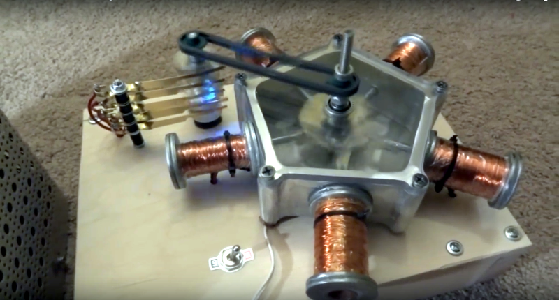
Radial engines are just plain cool – it’s inarguable that any tech that originated with early aviation is inherently awesome. But, what do you do when you want to build a radial engine in your dorm where a combustion engine would be inadvisable? For University of Washington students [Jeffrey Weng] and [Connor Lee] the answer was to power it with solenoids in place of the pistons.
The easiest way to approach a project like this would have been to use a microcontroller. A simple program running on an Arduino could have easily provided the timing to switch power to each solenoid in succession. [Jeffrey Weng] and [Connor Lee], however, took a much more interesting approach by controlling timing via a simple distributor. This works in the same way a spark distributor on a combustion engine would have worked, except it’s actually providing the power to actuate the solenoids instead of providing just an ignition spark.
Also impressive is what they were able to accomplish with such basic tools. Those of us who are lazy and have access to more expensive tools would have just 3D printed or CNC cut most of the parts. Either [Jeffrey Weng] and [Connor Lee] didn’t have access to these, or they wanted to increase their machining street cred, because they created all of the parts with simple tools like a band saw and drill press. We’ve seen some beautiful engine projects before, but what this build lacks in objective beauty it makes up for in ingenuity.
[Thanks Ali]


There’s a whole cult of Solenoid Engine makers: https://www.youtube.com/results?search_query=solenoid+engine
Take a look at this monster: https://www.youtube.com/watch?v=6HND4x22jXM
These have all the vibration and high moving parts count of internal combustion engines, with none of the energy density benefits. But very cool, in a retro-steampunk way.
i am surprised that they do not use electronics for timing and switching.
[facepalm]
why is that a facepalm? I like the cam system, but an electronic timing system with a simple IR or hall effect rpm monitor would be easy to build and would offer more things to tweak, not to mention be more reliable.
I get that it sort of ruins the tesla era steam punk aesthetic, but that isn’t so obvious that it requires you violate Wheaton’s law in response.
The V-8 in this video is cool to watch as well. I’m a sucker for sparks though.
https://www.youtube.com/watch?t=1&v=2wfo2QqkXMU
Very cool!
Think it needs some flyback diodes.
You say that like you don’t even *like* sparks!
this isn’t going very fast but for somethings that need to be fast like fuel injectors, you do not want flyback diodes because it takes much longer for the magnetic field to decay with such low voltage
The setup is more or less a very convoluted switched reluctance motor. In actual SR drives, the motor windings are switched with a pair of power transistors (usually MOSFETs or IGBTs, though HV HEMTs are emerging) and a pair of diodes per phase. Unlike conventional motor drives, a SR drive has the transistors in each phase switching on and off at the same time (except a “sustain” mode used at lower speeds, which is beyond the scope of this discussion). When both transistors are turned on, the winding is connected to the supply rail. When they turn off, the diodes redirect the flyback current back into the supply rail, to be immediately used by the next phase.
The real beauty of a SR motor is that the rotor is more or less laminated steel, no squirrel cage or magnets to hold in place. That makes it very well suited to very high speed applications, such as water cycle air conditioners that need the compressor to spin at over 100kRPM in order to get a usable flow rate with a such low vapor density.
You could make a really small one with piezo instead of solenoids.
There are some MEMS motors that work like that! (they use capacitors with mobile plates rather than peizos)
I work for what you could say is a very large “company” who has billions of dollars to throw around, and there is a machine shop or two, but the group of guys I work with, we more often than not use the band saw, drill press and various metal files to fabricate all sorts of assemblies and fixtures.
Machine tools are wonderful and super precise, but when you don’t need machine tool precision and setting one up takes more time and money than doing it the old-old fashion way, it just makes more sense to do stuff by hand sometimes.
Being able to make things by hand and being precise and meticulous at the same time are great skills for anyone to have.
All too often I see people on here that “hog-out” holes when they don’t have a proper drill, reamer or punch, they don’t bother to align the holes they drill, when a simple speed-square or printed out template would do them wonders. They use hand nibblers to cut square holes, that end up anything but square… They don’t “de-burr” anything, they don’t file rough edges and on and on.
And if you can’t hang with the details on that stuff, good luck with setting up the tooling on a CNC machine or getting decent prints from your 3-D printer.
But I’m happy to see that these guys have their stuff together. Very well made!
What method using hand tools would you recommend for making square holes? I’m interested because I have no space (particularly no “dirty” space like a garage) to set up tools, and recently did in fact use a nibbler to cut a rectangular hole (WITH A TEMPLATE) and found it possible but tedious.
Nicely built! I hope his setup has some really good power/mains filtering.. That sparkgap looks like a horrifing source of RF noise :P
Wow, nice, and it’s not 3D printed.
Snubbers connected across the contacts can help to reduce the arcing by providing an alternative path for those high voltage spikes. Also as one other person commented, add free wheeling diodes.
Lacks in objective beauty?????
This is beautiful!
It even sounded slightly plane-like when the engine started.
My god. I need that power supply.
It’s called a variac, and it has a non-isolated AC output. The entire volume of that case is filled with a toroidal transformer with a wiper contact attached to the knob, er, handwheel.
Useful for “electrical”-but-not-“electronic” things that aren’t picky about voltage or polarity (like this motor), and gradual power-up of non-voltage-regulated equipment like old vacuum tube gear with suspect capacitors, but these days nearly everything interesting that takes AC has a regulated power supply which is just going to trade current for voltage, or not start up at all.
That’s a pretty awesome build!
“…however, took a much more interesting approach by controlling timing via a simple distributor.”
It’s called a commutator, they’ve been around for almost 200 years. But yes, lets throw an arduino at everything and pretend that’s simpler.
Not necessarily simpler, but more robust in the long run. In all actuality it would much more complex to use a micro controller to run this. The real advantage of using solid state parts to replace the commutator would be elimination of a high wear point and a fair bit of RF interference.
Also note that I say micro controller rather than Arduino. Arduinos, while easy to use, are not the only way to skin the cat.
Nice build ! Loving the steam punk look and indeed impressive much like diresta’s way of working ;). Doubt it’s an efficient motor still way high up on educational factors!
If you ignore the actual engine, the whole video is basically 5 minutes of “Why you should own a Bridgeport”. I remember making stuff like that, but oh man, I got away from it as fast as I could. It takes so much more work to do it the hard way like they did!
I don’t need any more reasons to want a medium to large stationary mill, I have enough already! :P
I really like the spool-winding technique: https://www.youtube.com/watch?v=jeHNMjBrvLk&t=2m22s
1) Lay wire on floor
2) Measure and flag with tape
3) Wrap it up with drill
Beats all of the turn-counting devices (that I’ve never had the patience to build for a one-off project).
4) have the wire snag on something and it break it
5) remove wire that is now too short wire from bobbin, return to step 1) :P
It’s just a wheel and a revolution counter, it’s not rocket science, both can be scavenged from old tape players ;-)
Am I the only one to cringe when I see them hammering the vice handle?
No, you’re not. That was rather disturbing…
He may have been hammering, but he wasn’t using a hammer. It was a mallet. Mallets are made for “hammering” on surfaces without damaging them. When you need your vise (not “vice”) to be really tight, you either add a “cheater bar” to increase mechanical advantage, or you use a mallet. He chose the latter.
Electric planes here we come. :)
I also made few of them, awesome little engines.
https://youtu.be/1nQdl_rdr70?t=41
https://youtu.be/wYTlyxNkpnw?t=48
https://youtu.be/6BFIxs0umew?t=36
https://youtu.be/40YyGxJNaCs
https://youtu.be/eByellxSVrM
SparkFun should feature this thing.
I’m still waiting for a solenoid EV retrofit for gas engines. Drop in bore replacement piston drivers that are switched by the preexisting spark firing as a signal. Available for 350 SBC first. Bonus points if each compresses air enough to make a loud pop that combines with other cylinders in a reasonable facsimile of engine noise. :)