In material science, thermal expansion is a very well understood concept. However, in most cases it’s regarded as somewhat of a nuisance. It’s the kind of thing that gives engineers headaches, and entire subsystems of machines are often designed specifically to combat it. But a group of students at MIT have come up with an ingeniously simple way of taking advantage of thermal expansion to create shape-changing composites.
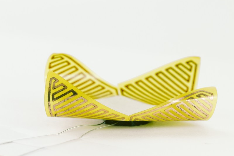
Their project is a method of creating shape-shifting composites, called uniMorph. It works by using resistive heating (or simply ambient temperature) to change the temperature of a sandwich composite. The composite is made of two different materials, and the copper traces to heat them. The two materials themselves aren’t particularly important, what’s important is that they have vastly different thermal expansion rates.
When the composite is heated, one material will expand more or less than the other material. Depending on the relative shapes of the two materials, this causes the composite to bend or twist in predetermined ways. How much it bends, for example, is just a matter of how the layers are cut, and how much they’re heated.
The concept itself isn’t exactly new – bimetallic composites have existed for ages. We even covered a similar idea that works based on moisture content. But, the methods used for uniMorph are very well thought out. It’s very inexpensive to produce, and the students seem to have devised reliable techniques for designing the layers in order to produce a desired shape change.
[thanks flxhbck]


Unfolding OLED displays, solar “flowers” open by day, closed at night, robo-goldfish?
robo goldfish is an interesting idea… water has tremendous heat absorbing capacity, so if the copper can heat it up enough to move, it’ll cool off very quickly once power is removed, but i don’t think it will be able to do quick, jerky movements like a fin, but perhaps slower movement like a jellyfish would be feasible. problem is it’ll be very inefficient.
Interesting use of existing technology. Printed circuits on Kapton have been around a very long time, so there’s nothing new on that side of the board. What’s new and possibly unique here is the application of a plastic with an intentionally different thermal expansion rate. It looks to me like an idea looking for an application.
I wonder how long it will last, more specifically how many cycles it can withstand before delaminating.
Anyone who owns a 3D printer has already experienced this effect at some point. Curling corners on the first few layers of a print are due to difference rates of cooling. When you apply a very hot layer above a layer that is cooling, the cooler layer starts contracting faster than the hot layer and it curls up off the bed. Basically it’s shriveling up. Most of us have solved the problem with glues to hold the layer down and heated beds to maintain a constant temperature.
While I’ve observed this happening, I don’t understand why it makes it curl UP. I always wondered if the hot layer that you’ve put on cools faster initially than the layer that’s been cooling for a while. Am I way off the mark?
Well, I know elastic bands on my underwear shrivel when heated and release when cooled. Maybe it’s like that?
I may be wrong, but I think the curling UP of 3D prints is caused by the fact the lower layer has already cooled and shrunk somewhat before the upper layer gets applied. Due to this the top layer cools (and therefore shrinks) more relative to the lower layer causing the up curl.
In the above photos both layers are probably heated uniformly but The difference in material causes the bottom sheet to expand more. The effect is the same, the top sheet is shrunken compared to the bottom sheet so it curls up.
Exactly.
Because the lower layers are cooled and more rigid along the XY than Z the tension from the shrinking pulls the outside perimeter of the print inwards and upwards. The forces add up as the print gets taller, which is why thin prints don’t curl as much as thicker ones.
On the first layers, the leverage is very small. They will try to contract when cooling, but the contact to the glass is strong enough to resist it. The upper layers, on the other hand, have much more leverage and thus are able to curl the whole structure until it separates from the glass.
Well what everyone else already mentioned I said initially, except for for the forces adding up part. If you take a printed part that has a wide bottom but not very tall, put it on a cold bed and begin heating the bed up and watch what happens. It will curl up. And the reason is because the lowest layers of plastic are heating and expanding, while the cooler upper layers are staying rigid, forcing it to flex upward rather than expand our evenly. I thought I could fix a printed part that had curled up in a corner by turning the heated bed on during a print and it curled all over.
Just for convenience the paper is here: http://tmg-trackr.media.mit.edu/publishedmedia/Papers/592-uniMorph%20%20Fabricating%20Thin%20Film/Published/PDF
They also mention using this material (rather affordable from Adafruit): http://www.adafruit.com/products/1894?gclid=CjwKEAjwnf2wBRCf3sOp6oTtnjYSJAANOfheyb2a9jELztVZrZkkLdE86tqDN3QRS2wWsVQ1L7Qt7xoCf2vw_wcB
How are they gluing them together? The paper mentions spray adhesive, but it also mentions a curing step that I wouldn’t have thought applicable? The paper is missing a lot of technical data that would be useful (thickness of materials?) Type and source of UHMW PE? What about LDPE (available everywhere: plastic bags and milk cartons) and HDPE (different plastic bags.) There are some UHMWPE tapes that you can buy.
I wonder if this works with really thin fiberglass PCB material (which is relatively common and probably much cheaper than kapton.) Presumably, the FR4 has thermal expansion similar to copper, just like the kapton, or it wouldn’t be a good PCB material…
Shoot; I may have everything I need to try this out…