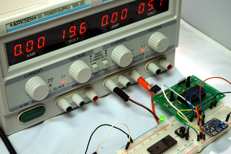
I recently picked up an Arksen dual power supply. You’ve seen these before, I’m sure, under a variety of names in places ranging from electronics stores to eBay. They look amazing for the price, and while I didn’t expect it to measure up to some of the pro supplies I have, I just wanted something to stick under my desk instead of having to move things to the bench or–worse–drag a heavy power supply over to my desk.
When I was putting together the sonic motion sensor, I found that the HC-SR04 module needed more current than I could draw out of an Arduino Leonardo. I figured this would be a good chance to use the new supply in anger. It seemed to work without too many problems. But there were a few things you might want to know if you have a similar supply or are thinking about getting a similar one.
First Impression
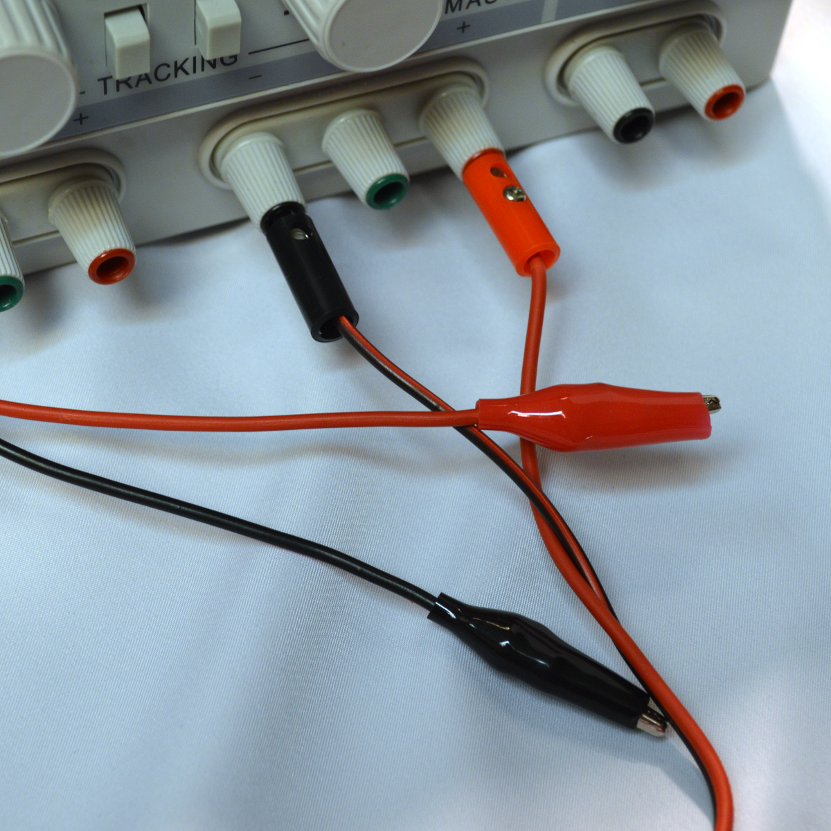 The thing is heavy. Really heavy. That’s good, though, since it is supposed to be a pretty hefty supply (5A at 30V maximum). A quick check with a voltmeter showed the voltage on the onboard displays was pretty close (within 100mV). The box came with one set of leads. These were essentially junk. Flimsy banana plugs with screw down connectors and very poorly soldered alligator clips (see right). They were eventually rebuilt and have been acceptable since then, but leads on a 5A supply ought not have 4 ohms of resistance!
Speaking of the leads, the binding posts on the supply have nice little color rings inside that indicate if the post is positive or negative (red or black). The problem is, on some of the posts the rings snap out nearly every time you pull a banana plug out of it. A little super glue will fix it, but it was certainly annoying to have to glue a brand new piece of gear.
The supply has several nice features including a current limiting mode and a mode that slaves one supply to the other in series or parallel. What is missing? There’s no sense input which would be nice if you need long cables (or want to use the poorly built cables that come with the thing). There’s also no way to read the current on the dedicated 5V supply without an external meter. However, for the price (about $130) you can’t complain about that much.
Smoke is Released
The power supply did a fine job of lighting up the HC-SR04 and I started getting the output I expected from the module. Until the next day. Something was wrong with the SONAR module. Replacing it with another got everything working the way it had the next day. Conclusion: dead module.
The SONAR modules are cheap, so some mortality on them isn’t that surprising. But just to be safe, I decided I better look at the power supply voltage when the unit is turned on and off. After doing that, I understood what happened to the SONAR module!
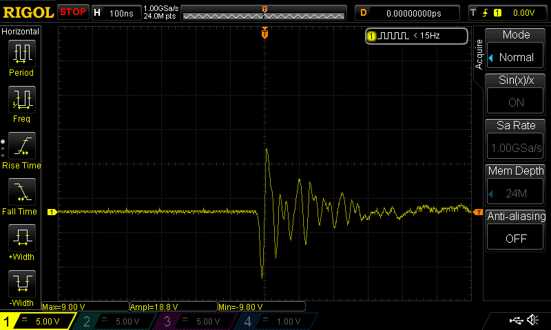 With the output capacitors discharged (that is, I touched the leads together), turning the unit on wasn’t too bad. At a 12V output setting, you can see on the right, there’s a little bit of noise starting up. The positive excursions aren’t bad although the nearly 10 volts of negative is a bit worrisome. Lesson: don’t hook up the load until after the unit turns on. There are several bursts like this before the voltage makes a nice gradual rise to the set voltage. The effect occurs even with a small load (an LED) connected.
Of course, I wouldn’t turn a supply on while it was hooked up to a circuit anyway. You ought to make sure the supply is set right before you hook it up. Of course, the supply remembers its last settings, but a supply with real pots could have changed settings while off. That’s probably not true with these supplies, but even if the power was clean starting up, I probably wouldn’t turn it on while connected.
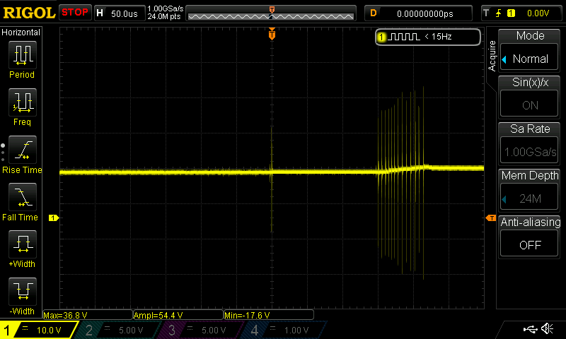 The real story though, is when you watch the supply turn off! You can see the output voltage is around 12V, but look at those spikes (to the left)! There are several bursts of them before the supply shuts down nicely. Lesson: disconnect the load before you turn the unit off!
With or without a load, these death throe spikes occur (and there will be several before the supply shuts down). Not all of them are as extreme, but they exceed the set voltage by quite a bit in each case I’ve observed. This is a problem because while I might not turn the supply on while connected, I would turn it off. Even if I decide not to turn it off, a little puff of smoke or other danger sign might have me throwing the switch off. I presume if the power goes out you’d see the same spikes on the output.
Inside
You can see some photos I took of the inside of the unit in the gallery below. The transformers are big and heavy. If you want to take one of these apart to adjust the displays or repair, it is good to know the handle’s back bolt attaches to the main chassis. So in addition to the eight bolts on the sides (four on the left and four on the right) that back bolt has to come out, also.
The build quality is about what you’d expect from something at this price point. I’ve heard people say, however, that the build quality of this class of power supply can vary wildly, so maybe this one sample point is not enough to draw a conclusion.


In Conclusion
Speaking of conclusions, would I buy this again? I’m not sure. It is certainly serviceable. I’m not sure how much it will drift over time or if I’d trust it driving a large load unattended. The output spikes on power off are almost deal breakers. If you had an expensive prototype connected to it and the AC power died, that could be a real problem.
It would be possible to modify the power supply, of course. Even a fast reverse diode across the outputs would clamp the negative excursions to some level (you’d have to make sure that you didn’t mess up the ganging of the two supplies, though). If you could rig a relay that would turn off faster than the rest of the circuit, it could disconnect the outputs before the turn off spikes occurred. A little turn on delay might help too.
Still, that seems like a lot of work. If you scour the surplus market there are some excellent major-brand power supplies (like Lambda, Power Designs, or HP) that are available for about this price, especially if you can reduce your current handling expectations. They’ll be highly used, of course, but they will also be well built and designed.
On the other hand, for what I wanted it for–a source of regulated power at my desk–it seems fine. I might smoke a $3 ARM chip or a $2 SONAR sensor when the power goes out, but that’s a risk I’m willing to take.


The assembly quality on these is abysmal: http://lab.whitequark.org/notes/2015-04-17/ground-loop-in-a-lab-power-supply/
I’ve got one of these in my junk bin. it killed a few logic chips – easy to replace but more time wasted than money saved. The fan was not plugged in factory-wise. This resulted in one dead channel, bad electrolytics (the foil with the ratings melted and the lid went up) etc.
A computer power supply gives a nice clean voltage at 3.3, 5 and 9 V. It shuts off when shorted, and can provide a ton of power. For most times I need power, this is perfect (so long as you can see how much current is flowing – easy to add with a cheap multimeter). I need adjustable high power outputs rarely enough that I don’t mind lugging my circuit to a lab with fancy power supplies.
Just be sure it behaves well without a load. Some PC power supplies can change to discontinuous mode if the load is too low, which can cause the output voltage to be a lot higher than anticipated!
A power resistor solves this.
Most computer power suppliers don’t give off nice voltages unless you put some load on the 5V and 12V.
They also usually break down on shorts in my experience. Not a huge problem, as you can get old ones for really cheap or free. (Told someone I could use them, got 10 for free)
In my experience, if you abuse them too much they tend to mysteriously stop working. I went through two before switching back to my homemade supply.
I’ve used them as ham radio supplies, but as daid303 said, you have to have a load across the 5v line. I used a 5Ω wirewound resistor which I mounted in front of the fan to keep it cool. You also need to add a serious amount of capacitance across the output. I used a combination of capacitors, including a 10,000µF 50v cap. Even with filtering on the output, the computer power supplies I used produced a ton of RF hash all over the HF portion of the spectrum, so they were only useful for VHF/UHF radios. They work in a pinch, but I quickly replaced mine with linear supplies from Astron, which work a lot better and don’t have the RFI issues.
I just used a turn signal light bulb for the 5v load. Actual sockets for those are too big to fit inside most computer power supply cases so I just unfolded the contact wires that wrap around the bulb’s base and soldered them right into a little piece of veroboard.
OR you have to fiddle with the feedback loop to only sense the desired rail.
One word of caution though – if you screw up the feedback loop, things will explode.
p.s. there’s also this way… http://www.qrp4u.de/index_en.html
Can the paired supplies track negatively?
(i.e. turning one supply to 5 Volts the other will go to -5 Volts)
Isn’t that just a question of wiring it a bit different? By that I mean just simply swapping the positive and negative wires going into the one you might want going negative v:
Pretty common to do on just about any reasonable isolated lab PSU…
usually the supplies are completely independent and not grounded, so yes.
Note that power supplies are are not good at sinking power. i.e: set on to 5V output and the other to 1V output (and connect the grounds), then place a resistor between them. The 5V supply will supply current to maintain the 5V, but the 1V supply may not be able to “sink” enough current to keep it’s “output” at 1V, it may rise all the way to 5V.
I’ve blown at least one cheapish power supply trying that trick :P
I see tracking under the mode switches so i would assume that it can. The knobs on one side are labelled ‘Master’ and the other ‘Slave’.
Yes. you can do this no problem. Both supplies (at least on the version I have which is a different rebranding) are floating so you can hook them up however you want. Series, parallel, whatever.
It is almost worth buying one to gut and rebuild.
Did you try to measure the turn on / off spikes with a load on the PSU? I wonder if you are picking up stray inductive spikes from the big transformers or something similar with the high impedance scope probes.
Yes, that’s quite a common error electronic noobs like the author are doing these days. Always be
aware that: “Who measures measures rubbish! Before you measure something you should know what you measure.
I think the quote ought to be: Who calls someone a noob ought to research that person first. I read stuff from Al when I was in college and that was longer ago than I care to say. I think most of us know where the rubbish is.
If I convert this to tlhIngan Hol with google translate, I might make sense.
A power supply output is a low impedance device so I don’t see how the high impedance of the probe can pick up noise from radiation when connected to a low impedance source. Don’t hesitate to revise your electronics textbooks.
Impedance is frequency dependent. Even a low impedance source can have high impedance if you have a long pieces of wires connected to it and have no decoupling at the far end when high frequency is involved. Connecting =digital chips without decoupling caps is bad practice.
FYI: there are decoupling caps on the breadboard and no bulk caps on either of two PCB. Also at bad probing techniques e.g. use of the long ground straps with scope probes can pick up high frequency spikes.
Yes as I mentioned the spikes are there even with a small load. I didn’t fully load it because, honestly, I doubt I will often be powering a heavy load with it. Drawing 20 or 30 mA on a small controller, it still ought to behave.
I bought a single output 5A 30V supply (X-Power brand, a clone no doubt) for about $60 USD a few years back, and it has worked very well for me. I haven’t tested it for spikes on power up/power down, but I am in the habit of disconnecting it from my work before turning it on or off anyway.
I have noticed that it’s output isn’t clean enough for AVR chips without adding some capacitance. I once spent several days trying to track down a weird set of faults on an Arduino clone board I built only to (eventually) figure out that it was noise on the DC input. One of these days I’m going to pop the supply open and add some filtering to it, but it does 99% of what I need it to now.
Problems or not, I think I got my money’s worth.
I wonder if it suffers from a problem similar to the original Korad design: https://www.youtube.com/watch?v=Fya-4mjV4N4
I bought one of those awhile back and after some initial testing, I have mostly decided not to use it, except for projects which are not as susceptible to power spikes. I found in mine that the issues occurred not just during power on, but also when the various internal relays switched around to construct the various combinations. The thing is almost junk, IMO. And I have chalked it up as being a $130 dollar lesson in doing more homework and less “wishing” when buying important equipment.
Yeah I didn’t test it when adjusting the voltage but that would not surprise me at all.
I have the Arksen 3 A version, the 303-2D. It has very low quality 1-turn potentiometers for current and voltage adjustment.
I desoldered the voltage adjustment pots and now I’m waiting for new 10-turn pots to arrive. This makes it possible to adjust the voltage more accurately, hopefully. I noticed, that the voltage adjustment pots are wired in such a way that high resistance results in high voltage. This is unfortunate, because potentiometers will tend to develop spots of high resistance when they age…
Actually, that’s a great suggestion. Thanks!
These are what I ordered: http://www.aliexpress.com/item/3590S-2-502L-3590S-5K-ohm-Precision-Multiturn-Potentiometer-10-Ring-Adjustable-Resistor/32441223426.html
I hope they’re at least a bit better than the original ones.
When I studied electronics, we had to build a power supply. Unfortunately we where not allowed to change the design :-(
It used a -3V reference voltage, that would quickly go to 0V when powered off, in turn causing a 3V jump in the output voltage.
my current power supply looks suspiciously similar ( http://www.a1gereedschappen.nl/Webwinkel-Product-58091573/Gestabiliseerde-regelbare-netvoeding-2-x-0-tot-30-volt-0-tot-5-Ampere.html ) but had a single ring-wound transformer.
I found it very strange that you have problem running that range finder module from your Arduino as it only requires 15mA. May be it was partially damaged already by the power supply?
I thought I had run them like that before, too. But it didn’t work at first without ever touching the power supply. Then the power supply got it working but later it was fried presumably from the surges. The knockoff Arduino Leonardo might be the culprit for the original situation.
Can any one recommend a better alternative? I’d love a single block design that can be connected in parallel or serial, similar to that design – just add another unit for more current or voltage.
Building a decent bench supply used to be like a right of passage for any tech/ee.
There’s nothing hard about building a linear supply and they last for aeons unlike SMPSU’s.
I have some here now and the next will be a re-wound MOT that has multi-taps (both hot and cold) to reduce dissipation at higher currents and lower voltages.
Precisely. and most people using small power stuff can make a low power kit for little money.
What surprises me is that there is not really any good quality small power stuff like dual 15V/1A (CC/CV) available on the market, outside of traditional manufacturers which charge a lot more.
LM316 or is that LM317 and a four in one op-amp chip along with the power components and case – done.
yes, plenty of adjustable schematics and kits out there, even from classic kits providers, there are many kits similar to this one http://www.electronics-lab.com/project/0-30-vdc-stabilized-power-supply-with-current-control-0-002-3-a/
I would stay away from ebay stuff, these kits are not that expensive in parts and …. well i have seen poor quality stuff from many such providers.
@tekkieneet For a first power supply, definitively go for something with current limiting, not just a LM317.
Adjustable DC power supply (bare board DIY linear kit without transformer or display or heatsink ) is available from China for around $14. I have seen microcontroller switch mode version with display and keys in the $20 range. There are also breadboard plug in types with fixed voltages at far lower price.
FYI: LM1083 3A/5A/7.5A adjustable supply chips that are similar to the old LM317. These are pretty easy to use and when design/built correctly can be a very good alternative to a bench supply.
Make that LT1083 (Linear Tech) part. http://www.linear.com/product/LT1083
Those lookalike binding posts with their tiny hidden when occupied color inserts aren’t even in order. The ground needs to be between the minus on left and plus on right. Since this critter needs to be disconnected every time, lookout for mistakes.
My experience with cheap eBay banana plug cables and crocodile clip cables (even USB cables) … they are total crap. Wires are too thin, usually not soldered or properly crimped so you can easily get few ohms using 20cm cable. Pretty crappy when you are testing for example LEDs and asking yourself why your 3A 5V source drops to 3.5V when using only 1A worth of LEDs. You can rework them, but in that case it’s easier to just order connectors and make cables properly.
I have one of these branded as Mastech HY3005F-3. It has an interesting problem. The slave (left) sides voltage is all over the place in independent mode when you minutely move the voltage knob. The slave side is stable if driven by the master (parallel mode). I suppose its the slave voltage pot that’s gone bad. The relays sure make quite a clacking sound as its randomly hopping from 0.5 – 12volts. Unsurprisingly, I use the master on my bench. Driving an +/- rails is ok as that is in parallel mode.
Pot has a bad spot in it most likely. Going from lower to open to higher resistance when it jumps the gap. I notice potentiometers that are old and have had the pot in a position in the middle, even in the junk box unconnected – will degrade at that point.
We used to carry a can (pressure pack) of “Pot Lube” in the tool kit for this. Pot’s have a small opening that you can spray oil into. WD40 or CRC will probably do fine if it has the little tume to get the oil right in. Spray and turn full one way to full the other way.
One other thing I have noticed is that sometimes the third pin isn’t used, it should be shored to the middle. That way when the center connector (wiper) goes completely open circuit … the total resistance is the maximum of the pot.
I agree with the others – bad pot. This gives you the opportunity to upgrade to some quality 10 turn pots so you can get finer controller of voltage and current. And maybe a hackaday post!
I can’t believe this is actually sold as is! (insert facepalm emoticon here)
These are all cookie cutter supplies that have been around for years now. A local community college has these for their electronics lab supplies under the Mastech label.
The ripple out of them is horrid under load or without. They have killed many unfortunate student’s projects no doubt. I think if you used it as a raw supply to drive a linear regulator like a good old LM78XX or a switcher if that’s your thing, you’d be ok.
I’m all for the used high end gear market. Even if its old and the beige case is turning more of a nasty looking yellow, the insides would survive a nuclear holocaust and still have minimal ripple and a graceful startup or shut down. Just make sure you read the auction description well. Sometimes error codes can equate to “unrecoverable garbage” or “refinance your house if you want to fix this”
There is solder spatter on the PCB, when you see that you know to not bother buying it.
Such shoddiness from over-speeding workers just means the thing WILL fry some of your devices at some point.
It’s a bit crap if it regularly zaps components. For power-on, perhaps add a time-delayed relay before the output terminals? For the power-off zapping problem, perhaps the same thing in the opposite order? IE have the power switch disconnect the output, then, after a short delay, switch the actual supply off. Actually a little 8-pin micro controlling a relay might do it, if you’re more of a digital geek than an analogue one.
You could even offer it as a mod, or an add-on, a little box to go between the supply and your load. Use a linear regulator to power the control circuit. People might buy them, after their first couple of circuits get zapped.
You shouldn’t have to unplug power supplies when you want to cut the power to something, cutting power, tweaking, then back on again, is a normal way (for me) to work on things. Except for mains power, of course.
Agreed, if you stick with the PSU then install a fix like that.
If the power supply have startup and power down glitches, chances are that the feedback loop is marginally unstable. You’ll never know if your load might cause it to oscillate.
Not really, it may just be that some discharged capacitors force drive into the main transistor. The one I posted above has protection at loss of AC. With a bit of tweaking in the values that protection can also be used at start up, eg delaying the rise of the negative supply will keep the output in off.
Ya I agree with spikes during power off it burns out my atmel programmer.so don’t connect your costly device to this .