A couple of days back, we wrote about the HACK – a prototyping platform designed by [Michele Perla] based on the Atmel SAM R21 MCU. It’s one of the new breed of devices consisting of an ARM Cortex-M0 MCU + IEEE 802.15.4 Wireless radio bundled together. This was exciting since we could pack a lot of punch in the HaDge hardware. We planned to use the same design later to power the HaDge. Building HACK would have allowed us to get it in the hands of the software team, while the hardware folks worked on the real HaDge layout.
The HACK design was ready for review and we asked around to verify the antenna layout, which was the part we were not too sure about. We asked Atmel for help with verifying the layout. That’s when we had the facepalm moment. They asked us – “What about FCC certification?” Since we plan to build the badges in quantities of a few hundred at the very least, it’s obvious we cannot escape from FCC certification. A design based around the R21 is ruled out – the cost of obtaining approval is pretty high. This means we need to punt the R21 and instead use an off-the-shelf radio module which is already FCC certified. Sigh.
Now the good news. This is a setback in terms of time, and effort put in by [Michele]. But beyond that, we’re good to go back to the drawing board and start afresh. First off, we decided to revert back to the Atmel D21 as the main controller. It’s a fairly decent MCU, and there’s a fairly robust tool chain available that a lot of people are familiar with. For the Radio, we are looking at some of these available options :
- https://www.anaren.com/air/products/24ghz-solutions
- http://www.nordicsemi.com/eng/Products/2.4GHz-RF
- https://www.adafruit.com/products/2471
- http://www.microchip.com/wwwproducts/Devices.aspx?dDocName=en535967
The last one from Microchip looks quite promising. But we’re open for better and cheaper suggestions, so please chime in with your comments.


How about these nRF51-based modules from Raytac – http://www.raytac.com/download/MDBT40/MDBT40%20spec-Version%20A3.pdf ? They seem to be FCC certified. I am using them for my of my project (which is actually a conference badge…) and Adafruit use them for their new Bluetooth modules. They are also the cheapest nRF51-based modules that I have found so far.
If you want something similar to the R21, look at the time cc2511. It’s got integrated USB, 2.4 ghz radio, and an 8051 mcu all on one chip. It seems to have some sort of fcc certification from its datasheet. The rfcat firmware for the cc1111 (think IMme and the new YardStck one) shouldn’t be too hard to port. The only drawback i see is that it’s the 8051 mcu can’t compete with an ARM.
FCC certification is entirely dependent on antenna design, anything with an IC where you have to make the antenna yourself requires re-certification to be sold, the IC itself will have cert but that does not carry over to the antenna which could make it behave oddly if not made right.
The CC25XX parts are rubbish for open source due to the closed tool chain. The IAR Studio costs a few thousand for a license.
For something that will run off batteries at some point, I think the Huzzah power consumption makes it not really appropriate. The nrf radio might be the best bet here.
I think the MRF24J40MA is interesting, the official modules are cheap and 802.15.4 and 6LoWPAN seem like they should be a good match for your inter-networks of badges idea, an IPv6 address for every badge! Though I think 802.15.4 and 6LoWPAN each view meshing as the other layer’s responsibility, leaving it totally unsupported if used together.
The nRF51/nRF52 having concurrent support for the proprietary “nRF24” 2.4GHz protocol (with support for meshing) and also Bluetooth LE at the same time would be pretty cool for compatibility with smartphones. Instead of having to setup some sort of specialized gateway router to handle routing a badge’s (or network of badges) 802.15.4 network to the greater internet you could allow any badge-wearer running an app on a smartphone to be an internet gateway for the badge’s nRF24 network. Plus BLE is supposedly getting 6LoWPAN and meshing support (and implementations), someday.
I think the nRF52 is being used in the new BBC Micro Bit also, which could have some appeal, e.g. a pre-made MicroPython port. It does kind of conflict with your desire to stick with an Atmel MCU though, since you probably don’t need two ARM MCUs on the badge (though the BBC micro bit does have two). And while nRF51 “modules” are readily and cheaply available from eBay, I’m not sure about finding ones that are FCC certified, much less ones with a nRF52 which doesn’t seem to be readily available anywhere yet.
I don’t really know anything about the Anaren module, but its CC25xx leaves a bad taste in the mouth. That chip’s radio SDK/binary blob is only usable if you buy a commercial compiler, it’s unlinkable with SDCC. I guess it could be an option if you’re OK with just having an untouchable black box on the badge…
I’m not sure why you’d go for a full blown Adafruit breakout board. Aren’t some variant or other of the ESP-12E modules FCC certified already, and smaller, and cheaper, and more well-suited to embedding on to another board?
Is part of the plan to try to spread the word of HAD/hardware hacking in general through the availability of badges at cons? WiFi would be the easiest protocol to interest other hackers with playing with at conventions, for sure, the rest all require learning at least a little bit of hardware knowledge to get to interfacing with. I don’t know if that’s a plus or a missed opportunity, though.
Like the other options, Wifi would still require setting up a router too, though wifi routers would be much easier to obtain for than some sort of custom 802.15.4 job. It would probably require its own wifi network apart from any provided for the general conference though, if only to make it easier to hard code an SSID into badges instead of making folks program every badge with a convention/hotel’s SSID, etc.
Yep, as nice as it is that wifi is making it’s way down to the micro and DIY level now, the need for an existing limited-range infrastructure network to join to is a big limitation.
Every few years, we’ll hear about “A project out of MIT” which intends to use WIFI radios in a completely adhoc/mesh way to do widespread internet. It is a damn shame that none of these radio manufacturers (BroadCom all the way down to Espressif) haven’t made a transceiver with all the bits and pieces exposed to actually accomplish that
I won’t be anywahere near these boards sadly, but i really agree with you. The wifi esp option seems way better.
There are at least two different fcc approved nRF51822 models: red bear labs offering and the rfduino. They can easily be programed in the arduino idea or using GCC and Nordic ‘s sdk.
Wifi is very high power draw. If you are going to use two AAA’s, it’ll work. If you want a coin cell, nah. This is why 15.4 radios were invented. (Too bad no one ever implemented 6tsch / 6lowpan in a totally in-the-clear implementation :\ OpenWSN marches on towards that, though!)
There is a RasPi 15.4 module that uses the highly featured AT86RF233, and is cheap … cheap enough that they are probably selling it without FCC cert :\
http://openlabs.co/store/Raspberry-Pi-802.15.4-radio
EMW3165 might be a candidate, but has the same high wifi power problem (has there been a “new part day” on the WifiMCU incarnation of that, yet?).
Are you married to 15.4? BTLE / Bluetooth Smart would be a pretty good choice, since it will about people to easily interact with their phones, since many include BT4.0 now. Phones could act as BTLE->IP bridges, too. For 15.4, you’ll need *another* device to bridge 15.4 to IP.
Consider Simblee, since it is a complete system-in-package, including antenna (!!) and I believe the creator is doing a ton of middleware to do novel stuff and the endpoint display: https://www.simblee.com/
Just ship the thing with a solder bridge unconnected, and leave it up to them to convert it to a working radio module. Nuts to the FCC and the incompetent federal government. It is ISM band and +0 dBm, they shouldn’t put themselves in the way of that.
I’ve been following Simblee for some time now. It looks awesome on paper… but I doesn’t seem to be available yet.
Its available NOW!!! Just launched in mass production.
Cool. Link?
I’m curious what the cost is for that kind of device. Getting a non intentional broadcaster device approved cost me $1800 plus a few revs of the board. I know communication devices are more, but I’m not sure how much more.
The fees + engineering time for FCC cert for a device that is an intentional radiator is on the order of $100k. This is why people generally use pre-certified modules, instead of going through the cert process themselves.
Not sure where your estimate comes from, but the two most recent FCC certifications I was involved in were both under $20k, including third party validation testing. Both were for 2.4GHz band products.
Have a look at the EZ-BLE PRoC / EZ-BLE PSoC modules from cypress. They can only do bluetooth le, but they’re small and reasonably priced (although, to be honest, you might ultimately be looking for something even cheaper). Their development software is absolutely brilliant. The PSoC/PRoC is an arm cortex m0, so maybe no other MCU is required, but you could always flash the PSoC/PRoC module with some small program to translate serial/i2c/spi commands to bluetooth signals and vice versa.
Wow, those do look pretty neat, < $10 in qty 500 , http://avnetexpress.avnet.com/store/em/EMController/FPGA/Cypress-Semiconductor/CYBLE-014008-00/_/R-5004565311686/A-5004565311686/An-0?action=part&catalogId=500201&langId=-1&storeId=500201&listIndex=-1&page=1&rank=0
For adding drop-in communications, that is pretty neat. The only thing is … they seem to only offer software for android/iOS interoperation. If there was a SAM R21 module, then you could use Atmel's lightweight mesh library right out of the box.
And the BLE PSOC dev kit package is neat and very reasonably priced too, and their commitment to making a ready-to-use module is awesome. But I believe the chip can *only* do BLE, and trying to use BLE for a badge to badge network or even a badge to convention-wide network doesn’t seem like a good fit.
That really makes it a lot weaker than the NRF51/52 option for this application, since the nordic chip is able to run a NRF24-protocol (“Gazelle”) mesh network for badge to badge comms and then using BLE for badge to phone (and phone to internet) comms together.
Another bluetooth option is TI’s new CC2650 which can run both a 802.15.4 network and BLE together. TI seem to be doing a marketing push about the CC2650 being able to manage both networks ‘simultaneously’, which might mean it might be easier to use than the NRF’s timeslotting system for handling multiple networks. But I don’t think TI have any certified modules available either, aside from the new SensorTag.
> trying to use BLE for a badge to badge network or even a badge to convention-wide network doesn’t seem like a good fit
It seems like some people have designed mesh comms on top of BT4.0, although who knows how well they work or how hard they are to implement: http://blog.bluetooth.com/range-limitation-what-range-limitation-introducing-mesh-networks/
I looked at that but have decided to test the Silabs Energy Micro based module BGM111 in my next design. Looks higher quality than the PSOC module and is <$8 in qty 10.
Been impressed with the Gecko series before so hopefully this module will also be good.
If I wanted mesh I'd be going with nrf51822 too, though the modules for that appeared to be either cheap or approved, not both!
CC26XX could be a good choice, but it's too new to have a selection of modules, hopefully it will get the same traction as the CC25XX did.
Atmel BTLC1000 is another bluetooth contender but haven't seen any modules for that either.
Isn’t the ESP-12 module used on the Adafruit board itself FCC certified? So can’t you just use the module by itself? It’s certainly cheap enough. Or am I missing something (again).
Ah yes, here it is. http://fcc.io/2ADUI/ESP-12
Someone probably should’ve known about FCC cert when making an RF product (any modification to anything needs to be re-certified…); but that’s ok, we all feel like idiots on the daily and then hopefully make some good headway (had a good day today lol).
Nordic or Microchip is your best bet (based on your choices), I would check out Freescale too (I don’t have a part number, sorry) where they can get some serious range and then you can attach another antenna to the PCB antenna to make it even longer. But I don’t think you need that for a conference badge.
I’m sure you guys are putting an RF switch inbetween the D21 and whatever RF chip you use? That way you can turn off the RF chip completely on downtime and save that current.
Wish I could help you guys more but I barely have time to breathe these days, looks fun. Keep posting updates.
Actually scratch that on the RF switch. These badges need to be on all the time since there isn’t a separate receiver. Hmm, get a good battery. At the 10’s and below uA range you guys should be fine. The display is killer though, that’ll push lifetimes down quite a bit, maybe only turn on screen when you’re within 50 feet of someone or something like that based off signal strength (Microchip should have something for you to use I bet).
Reading through the ESP12 module FCC test document, one of the things that they specify is that the end user is not to modify the antenna… So no RF connector for another antenna if you don’t want FCC on your back.
You don’t need a RF switch. Just need to isolate and cut off the power to the RF chip’s power with a MOSFET or power switch IC. You might also want to drive all the I/O signals to the chip to ‘0’ too.
ESP12 is too much power anyway, and for a conference badge any antenna addons are probably unnecessary.
And turning off the RF completely is dumb too eh? That won’t work since there’s not a separate powered receiver always on, it needs to stay in sleep mode at the least. And aren’t most pins by default tri-stated these days?–It’s smart.
Tristate is only valid when your chip has power… Depending the type of I/O pad, there are usually ESD diodes to the supply rails unless it is specifically engineered for hotswap or 5V tolerant (with its own local zener diode). So power can leak via I/O to the ESD diode to the VCC rail. This is answering to your “RF switch” which is a lot more complicated that it needs to be. There are usually power down options on chip these days, but some chips might still uses a bit too much power.
You missed the point about what I said in the ESP12 report. What you said: “then you can attach another antenna to the PCB antenna to make it even longer” is *exactly* not allowed.
The D21 in this case will always have power unless you have 2 dead chips lol. Yes I know about the ESD diodes, or the TVS ones. It’s much less critical these days. And I said disregard the damn RF switch, it won’t be needed here. And I didn’t miss your point about the ESP12, I said disregard that too, I never said put an antenna on that chip. Where are you seeing this?
Are you thinking this thru or are you just seeking an argument?
Just pointing out basic to *everyone else* who might not know the subject. You don’t have to b e a jerk about it.
Oh whoa whoa wait a minute, no don’t make me feel bad. *You’re* the one who always loves loves having engineering pissing contests (don’t mind most of them, so long as technically accurate) that usually come off pretty dickish. I think you were just trying to argue w/ me for no reason, that’s all; sorry if that came across jerky.
I assume you do know that you need TWO FCC certifications for something like this. The first is the radio part you mention, but then you also need Class B certification on the rest of it.
…Tiger
I’m just throwing this out there, but there’s also the HF-LPB100 by High Flying. Another Chinese module similar to the ESP-12 and only a little more expensive than the ESP-12 module. With FCC certification, but without the ESP8266’s developers community.
http://www.hi-flying.com/products_detail/&productId=68f4fd7b-39f8-4995-93ab-53193ac5cf22.html
Proprietary processor, just an AT command set and no open source development tools that I know of. :(
But they have a US supplier and is available with a trace antenna, U.FL connector or SMA connector.
http://gridconnect.com/low-power-wifi-module-hf-lpb100.html
FYI: for some reason the Decawave DWM1000 modules aren’t able to be FCC certified as there’s no onboard processor? This probably has to do with the nature of IEEE802.15.4-2011 UWB.
http://www.decawave.com/products/dwm1000-module
http://www.decawave.com/content/dwm1000-certified-eg-fcc-ce-etsi-compliant
http://www.decawave.com/sites/default/files/resources/apr002_certification_guide_usa_v1.0.pdf
And I would have thought the idea of a giant accurate self position tracking mesh network would excite or scare some people. Although that’s quite the guide for the steps necessary to achieve FCC certification.
Hi,
You’re correct, our module is not certified because no processor on board.
But nothing to do with the nature of UWB, the goal for Decawave was to do an RF only module that anyone can plug easily on its favorite MCU board with the proper mix of memory/peripherals for its application.
Otherwise, no problem to pass FCC with our chip our module. If you want to know the regulations and procedures you can have a look at our app notes on the topic: http://www.decawave.com/support
Mickael.
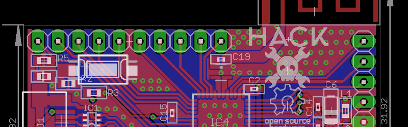
Based on the partial PCB layout above, there are a couple of potential RF issues. Yes I know you won’t be building RF on this board.
– read up TI AN043 on 2.4GHz PCB antenna layout. There are not enough clearance between the antenna and ground.
– most of the part has solid ground which is good. However the power track that feeds C2 basically cuts up the ground plane and now signals passing over the discontinuity which now becomes a slot antenna. The alternative is to run that track on the top side. Anytime you have a digital, watch where the return path is.
Don’t put silkscreen over control impedance for RF. :P
And after FCC please look into CE certification… We in Euroland wanna play with it as well… ;)
Can’t you just sell it as a kit? Would that mean FCC requirements do not apply?
I’m the EE on a smart watch project about to launch using Dynastream N550M8CC modules (nrf51422 based) that are already FCC certified. They are small and surprisingly easy to solder despite being a LGA-49. Data sheet is here:
http://media.digikey.com/pdf/Data%20Sheets/Dynastream%20PDFs/N5%20ANT%20SoC%20Module%20Series.pdf
How about the RFM73 or the newer RFM75? They are compatible with the NRF24L01, but lower cost. I get them for a bit over 1EUR when buying 25+.
http://www.hoperf.com/rf/2.4g_module/RFM73.htm
Just sell it minus the RF, users would have solder the chosen module to the board.
Thanks all. There’s some solid and useful references and links you folks have posted in the comments – keep them coming. We’ll follow them up and chose one that suits us best.