
It used to be a major rite of passage for a hardware hacker to acquire an oscilloscope. Until recently, new instruments were rarely in normal people’s budgets, so you probably made do with a used scope. Now, there are lots of inexpensive options, especially if you include low-end PC scopes and “scope meters.” Digital meters are also now inexpensive (often free at some major stores), along with signal generators, frequency counters, and even logic analyzers.
But there is one piece of test equipment you don’t see as often as you used to and its a shame, because it is a very versatile piece of kit. Admittedly, if you aren’t doing wireless work, it might not be high on your wish list, but if you do anything with RF, it is not only a versatile tool, but a good value, too. What’s it called? That depends. Historically, they went by the name “Grid Dip Oscillator” or GDO. Sometimes you’d hear it called a “Grid Dip Meter” instead. However, modern versions don’t have tubes (and, thus, no grid) so sometimes you hear them now called dip meters or maybe just dippers.
Why Does it Dip?
 Regardless of what you call them, the theory of operation is the same and it is pretty simple. The instrument is nothing more than a very broad band oscillator with a way to couple the output to an external circuit. There will also be some way to monitor how much power is being taken out of the oscillator. This is most often done by looking at the peak amplitude of the oscillator.
The reason for the dip has to do with the way inductors and capacitors behave at different frequencies. Just about any circuit or component has three sources of impedance: the resistance, which shouldn’t change based on frequency; the capacitive reactance, which is due to–of course–capacitance; and the inductive reactance from inductive elements. In some cases, you only have a significant amount of one of these. For example, in a carbon resistor, you shouldn’t have very much of either type of reactance. A capacitor should be predominantly capacitive reactance.
Reactance and Impedance
For a given capacitor, the reactance is very high at low frequencies and very low at high frequencies. Inductance is the opposite: low frequencies produce a lower reactance than higher frequencies. It is pretty easy to remember this if you think of a DC current as a zero Hertz wave. An inductor (a coil of wire) will clearly pass DC (low reactance) and a capacitor (two parallel plates) will clearly not pass DC (high reactance).
Even though the total impedance of the circuit depends on these three elements, it isn’t as simple as just adding up the values. That’s because resistance and reactance aren’t the same kind of quantity. If you have a 1V signal going into a 2 ohm load with 3 ohms of reactance, you’d like to know it would behave the same as 1V going into an ordinary resistor. If the resistance and the reactance are in series, the value of that effective resistor is the impededance and it is the vector sum of the resistance and the reactance.
In the example, then, 22+32=13. The square root of 13 is just around 3.6, so the magnitude of the impedance is 3.6 ohms. To complicate things further, inductive reactance and capactive reactance tend to cancel each other out. It is customary to treat capacitve reactance as negative, although since we will square it, it really doesn’t matter which one you consider negative to do this particular calculation. For the math inclined, you are really treating the resistance as the real part and the reactance as the imaginary part of a complex number. The conversion to polar form gives the magnitude and the phase angle.
In parallel it is sort of the same thing but the reactances add just like resistors in parallel. Here’s the point though: At some frequency, the inductive reactance and the capacitive reactance equal. In a series circuit, that means the reactance goes to zero and all you have left is the resistance. In a parallel circuit, the zero winds up in the denominator of a fraction, and so the effective reactance is infinite (and, in parallel with a pure resistor, doesn’t change the value of the resistor). Either way, reactance cancels out leaving pure resistance.
Resonance
The point where the reactances cancel each other out is resonance. The dip meter works because at the resonance point, the meter’s oscillator will have the highest load on it (lowest impedance), and thus the voltage will drop (or dip). At any other frequency, some reactance will be left and the total impedence of the circuit under test will be higher than at resonance.
Clearly, the most basic function of the dip meter is to measure the resonant frequency of a circuit. If that were all there was to it, it would be pretty useful. But with just a little extra effort, the dip meter can do so much more.
What Can you Measure?
First, it can also measure other tuned circuits, not just capacitors and inductors made from components. For example, antennas, crystals, and transmission lines can all have a particular resonance points, and the meter can measure them. For a crystal, the frequency is the one the crystal should oscillate at (with a little error based on loading capacitance and other factors). Antennas may be resonant at more than one frequency, not just the one you are interested in, so some judgement is required. Anything that doesn’t have a coil (like an antenna or a crystal) will need a little wire loop to couple energy from the meter to the circuit.
For transmission lines, you can measure by making a small loop to couple the dip meter (the smaller the better). Search for the lowest dip, and that will show the 1/4 wavelength frequency of the transmission line. For example, if the cable is resonant at 7.5 Mhz (40 meter wavelength) then the cable is about 10 meters long. Don’t forget, however, to factor in the transmission line’s velocity factor. That is, a quarter wave transmission line with a velocity factor of 0.66 will be shorter than the theoretical length (it will only be 66% as long, in this case).
Of course, you can use the transmission line relation either way. That is, you can get the resonant frequency to measure the cable, or you can set the frequency and trim the line for a dip. In fact, using what you know to get what you don’t know is generally a good principle with the grid dip meter. Want to measure an unknown capacitor? Resonate it with a known inductor. Or start with a known capacitor and find the value of an unknown coil.
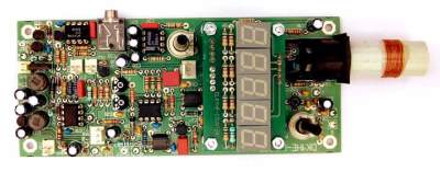 One of the main problems, though, is reading the frequency accurately enough. Some modern meters have digital displays (like the DipIt shown on the right). Most common meters, though, don’t. On the other hand, you can easily couple them to a frequency counter or use a receiver to determine the frequency accurately.
If you don’t mind a little estimation, you can do even more measurements. Coils have a Q (quality factor) that indicate how much resistance they have relative to their reactance. Using a good reference capacitor, form a resonant circuit and dip the meter. Note the frequency. Then tune the dip meter down until you find the frequency where the meter reads about 30% higher than it did at the dip. Now tune the dip meter up, through the dip again, until you find the 30% mark again on the other side. The Q will be roughly equal to the dip frequency divided by the difference between the two 30% frequencies.
It might be obvious, but the dipper can also just be used as a signal source. For example, to repair a radio, you might put the dip meter at a frequency the radio should be able to hear and trace it through the circuit. Many dip meters also have a mode where they will turn off their oscillator and use the coil (and tuning capacitor) along with a diode to act as a wavemeter. The meter, then, shows the strength of RF energy at the tuned frequency. Some meters even have a headphone jack so you can listen to the signal (making it almost a crystal radio).
Finding a Dip Meter
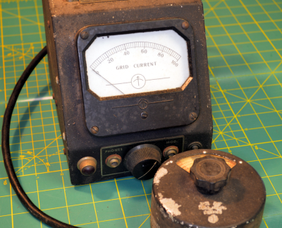 One reason many people don’t have dip meters today is that they aren’t as readily available as they used to be. Heathkit was a very popular supplier for dip meters and had several models. Other popular older models (often found on eBay) were Eico, Millen, Boonton, and Measurements Corporation (be careful, though; the ones with tubes are probably not a good deal unless you are a collector). You can find a list with pictures of many GDOs at [n4xy’s] web site (the pictures are a few clicks of the next button away from the main page). To the left is a picture of one of my old Measurements GDOs (and, yes, it does use tubes).
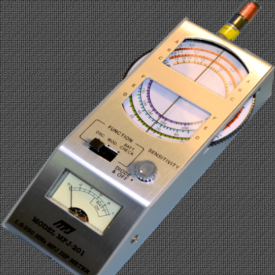
You can still find new dip meters from MFJ (they sell the MFJ-201 shown on the right, and you can also convert some of their antenna analyzers into a serviceable dip meter). There are also plenty of plans on the Internet. If you want a real tube model (not recommended) [w4cwg] has plans. A more modern FET design that has a novel bridge to help make the dip deeper is available from [SM0VPO].
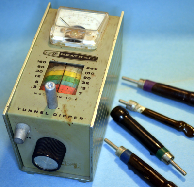 On the other hand, it seems a shame to build a new unit without a digital display. You can add one, of course, or you can go with one that is integrated like the DipIt or the ELM. There are plenty of other project and even kits out there. Look around. The hardest part, usually, is winding the coils, although some will call for variable capacitors that may be hard to match. Really, though, any oscillator that can be made stable will work. In fact, I have two old Heathkit dippers that use a negative resistance tunnel diode as an oscillator (one of them is in the picture to the left).
If you want a video demonstration of using a dip meter, I couldn’t do better than [w2aew] already did, so you can find his video below.


One of these has been on my “wish list” since I got my amateur radio license in 2008. I have yet to come across one at a price I could afford.
Also, I’m curious as to which stores are giving away digital meters? I could use some ultra-cheap DVOMs to use as power supply voltage displays (I would never trust a cheap meter for anything else).
Harbor Freight often gives away very bad meters. I sometimes pick them up and keep them at my desk since about once a week someone comes in and says, “Do you have an ohm meter?” I just give them one and don’t expect it back. The only problem is the ones I get don’t have buzzers. They are total junk, but for giveaways….
Thanks, I’ll look into that.
I have several Fluke meters and even an old HP 3457A that I rely on for proper measurements, but having a couple of cheapo meters to use as low voltage displays in my various power supply projects would be handy.
I find that automotive magazines, such as Hot Rod, Car Craft, and such often have a Horror Fright ad near the back pages. Often there will be a “Free” coupon (with $10 purchase) for their cheap meter. I love them, I have about a dozen of them, One for each vehicle, one for my desk, one for my workbench, plus about 5 in reserve. In the 5 or so years that I have been “collecting” them, have I noticed any problem and that was this summer. While working on something, (I don’t recall what) the reading (whether DC volts or Resistance) would blank out after a second or so.
By “blank out” I mean that it would drop the reading and go to 0.00 or OL. I tried changing the battery with another 9V
I had laying around, but it gave me a Lo Batt warning. When I put the original battery back in, it started working okay.
Horror Fright also sells another DVM for about $25, (I got mine on sale for $20). I keep it in my backpack, but the tilt adjustable LCD is sometimes doesn’t work in the flat position.
I also own 4 Flukes.
off topic, it is not about DMM at all, and OL means overload, this is normal for
resistance and non seen at all called infinity and normal
in volts it means too much voltage to the selected range, the manual for you meter covers this.
RTM?
the top is grid dip meters. only.
I inspected several of those red Harbor Freight meters that I got free with coupon. Terrible construction, I would not use them in high powered circuits. Solder balls and solder strings everywhere, the fuse is merely a glass fuse. No fuse at all on the 10A inputs, nonstandard banana jacks, leads are far too thin for 10A and the insulation is way too thin for the claimed 600Vac/1000Vdc.
A friend of mine didn’t look closely enough at his meter before checking a 240V dryer outlet. He still had the leads plugged into 10A, and the meter exploded. I mean literally a very loud bang, flash, and the halves flew apart. Fortunately he wasn’t holding it, and fortunately the leads that he was holding did not melt through.
well that’s not the meters fault that’s classic operator error
I think I spend $15 for mine at some hamfest. There are plenty of designs for building them using FETs online too if you Google it.
You can buy digital multimeters for 5 pounds in Maplin in the UK. Maplin are an electronics supplier who REALLY aren’t known for their bargain prices! They used to sell mostly components. Now my nearest branch, in an out-of-town shopping estate, with Maplin having maybe half a football pitch of floor space, doesn’t stock more than 2 of each type of transistor. As in, 2 transistors. Two, separate transistors, 2 bases, 2 collectors, and the other one. The rest, you can order in to the branch.
Kind of pathetic. The rest of the shop is filled with Chinese tat that you could get better and cheaper at a proper consumer goods place, as well as the novelty-gift, Chinese toy quadcopter type of thing. All very cheap in quality, very expensive in Maplin’s retail price.
Like Radio Shack just before The Fall, I think. It’s a shame, used to love Maplin, their annual component catalogues were like porn as a teenager. 500 pages or more, big lists of components! Now it’s all crappy PMR walkie-talkies, and outdated PC motherboards for 60% more than you’d pay at an independent supplier. No mobile phones though, for some reason. Those are still the domain of specialist phone shops, mostly.
Anyway what I’m trying to say is, apart from Maplin murdered my dreams, is that even a ripoff joint like that sells 5 quid multimeters. Other places might be chain DIY shops. Or of course, online. You can get really cheap multimeters. Sometimes they call them “home electrical testers” or the like, so as not to make the more expensive meters look, well, expensive. I’ve had a few of the cheap ones over the years, no complaints. Transistor tester built in too, usually. Everything a more expensive one has, in fact. I dunno what the difference is. I suppose build quality. Mine have never taken a knock, so they’ve been fine, over the years.
Besides those though, if you just want something to put on your power supply, you can get LED voltage / current meters for pretty cheap too now on Ebay. Often just an uncased PCB, suitable for mounting how you like. Your choice of colour for the 7-segment LEDs (that’s right, you don’t HAVE to have blue!).
Not quite free, but near enough that you could afford a good few. I think if anyone was giving them away free, it’d be one per customer, and only with a suitable purchase.
You can make something so much better, now. An Arduino can sweep the output from a DDS. The AD9851 can go up to 60 or 70MHz. Higher frequencies can be reached with frequency doublers and triplers. Logarithmic power detector can measure the signal over a very wide power and frequency range. A reasonable touchscreen LCD display to show the frequency response.
Here’s a video with great info that I thought I watched before and just happened to come up for Duplexer/Cavity Filters via YT AI and I was like… this Grid Dip meter came to mind:
https://www.youtube.com/watch?v=RI8u8L0RvQI
Gosh. I’m obviously not any sort of a hacker at all. I can’t recall having ever heard of a dip meter (I made my first electronic project over 50 years ago – it was a crystal receiver – no batteries, just a long wire out of my bedroom window to get that stuff out of the ether)
This is why I read Hackaday, for new learning…
Thank goodness, I don’t need to use one. Stuff like the ESP8266 IOT tinkering keeps me busy enough without going into new areas.
Anyway, thanks for a very interesting post.
Still have the grid-dip meter I was given when I was a kid just starting in RF. Fun!
Just curious why a vacuum tube dip meter is “not recommended”?
Well, I have a couple, but if you are just starting out and you want an actual usable instrument, you probably don’t want to deal with tubes and a bulky back end unit when there are excellent solid state alternatives. Now if you are collecting, that’s different.
Tubes degrade over time and aren’t stable in their behavior because of that too AFAIK, because they use a glow wire and they suffer from deposits.
Couple that with having them in an old device and the results are probably not what you want.
That’s apart from them using way more power and being bigger of course.
Your theory on tubes is incorrect for the most part: The “glow wire” (properly called the filament doesn’t suffer from deposits. This is a fallacy and you have the details conflated anyway, transmitting tubes can suffer cathode stripping at high voltages without proper heater current provided first. This doesn’t effect receiving tubes. Secondly, tubes run for upwards of 5000 hrs if you are using a meter that much my hats of to you. I have test equipment from the fifties that was in daily use in universities and labs with original tubes. And lastly, there is no disadvantage to a tube dip meter and some people feel they vacuum tube is actually bet than a few or tunnel diode at spotting the dip due to cutoff characteristics of tubes. I recommend you pick up a cheap tube one with an analog meter and if you decide you need the bells and whistles of a digital display go for it.
I have a Measurements 59 dip meter which I recently restored to “new” condition. I installed an SMA connector on the side of the enclosure of the oscillator and a “sniffer” inside close to the 955 oscillator tube. My StarTek digital counter precisely reads the resonant frequency of my antenna traps or any other inductor when the dip occurs; its original analog scale is still surprisingly accurate. Not bad for a 70 year instrument which is very easy and fun to use…
Tubes make simple GDOs, and I never had a problem one with an external supply. If one could dig up a Nuvistor, that could make a small package.
Some problems with sold state “GDOs” is bipolar transistors weren’t a direct equivalent to a tube, and early transistors of course lacked gain and higher frequency response. I don’t know how well the Heathkit tunnel dipper worked, but it too was a different device. So lots of units post-tube used other methods to see the dip. Jfets came along, and were like low voltage tubes, the gate dipped like a grid dipped, and MOSFETs came along which should dip too, but often saw an RF detector to watch the dip. In late 1971, someone from Millen described the process of turning their famous GO into a sold state unit, using a MOSFET. Same chassis, coils and tuning capacitor. Suddenly a “simple” tube circuit required lots of work, including multiple RF chokes to get it o tune without false dips.
I’ve never built one, but it seemed like a tube one was simple while a sold one became more complicated.
I think GDOs faded because other test equipment came along. But the price went up too. A Heathkit or Eico was cheap, while recent ones are in the hundred or more dollar category.
Michael
Because vacumn tubes have been deprecated since the 60s?
In hobbyist circles maybe, but tubes are still very much alive and well in high powered TV/UHF and Microwave/Satellite applications… #NotAllTubes
TWTs were replaced with FETs in satellites 30 years ago. Cant change tubes in space.
You might want to check that statement.
http://spectrum.ieee.org/semiconductors/devices/the-quest-for-the-ultimate-vacuum-tube
Neat article Techmonkey. Thank you for that link.
They usually need power supplies over 50v. so you need to know how to not kill yourself with that.
It’s really really hard to kill yourself with a transistorized 9v. radio.
In my experience, vacuum tube dippers worked *better* than solid-state ones. My Eico is good, and the Millen dipper was great. The Heath transistor dipper was only fair, and their tunnel dipper was poor. So as long as you find one that works (or that you can fix) age should not be a factor.
A good dipper can “feel” a resonant circuit from several inches away… it doesn’t need to be inserted right into the coil as in the video. Also, the meter should be relatively stable as you tune it from one end of the band to the other. Poor ones tend to have many false dips.
Dippers are good for revealing what is *really* happening in your circuit. Every capacitor also has inductance, and every inductor also has capacitance. This means they self-resonate at some frequency. Above this, your bypass capacitors turn into inductors and so are worse than useless! The dipper can also reveal that your circuit has parasitic oscillations at surprising frequencies, or that it is abnormally sensitive to RF of some particular frequency.
Found out that the spring in the stapler on my desk that happened to resonate around 5.490 GHz and was causing problems with my laptop when it was on our 802.11n network and I set it down near my stapler. The stapler was made of various metals and the spring was coated in some kind of non-conductive material, so it made a very basic radio (A power source from the odd metals, a conductor by way of the spring, and a capacitor from the gap between the two halves).
I only found out about it after messing around with a Dip Meter while waiting for some long-running jobs to complete at work.
It is possible to use other instruments as a Dip Meter. I have a page on my blog about using a Scalar Network Analyzer with a Return Loss Bridge to get a dip meter function. http://kv4qb.blogspot.com/2015/06/sna-jr-as-grid-ddip-meter.html
You could also use a Signal Generator ,diode detector and a RLB to get some dip meter functionality.
DuWayne
Just build one
http://213.114.140.60/use/gdo.htm [sm0vpo.com]
Don’t forget the drip pad in case it leaks.
Sheese, drip PAN!!!
Hey, I bought this same Heathkit meter off ebay a month ago. Couples well for tuning antenna traps, but the oscillator does move around a lot when watching it on an sdr waterfall. I found that setting the oscillator amplitude as low as possible and still seeing a dip helps get a repeatable measurement. Doesn’t put out enough signal for the cheap handheld frequency counter to pickup.
The circuit under test will “pull” the oscillator in the dip meter to a certain degree, so it’s best to use the weakest coupling that leaves the dip visible for most accurate frequency estimation. I have a Lodestar GDO and while I don’t use it often, when you need it it’s really the only tool for the job.
Isn’t this just an analog spectrum analyzer? Couldn’t one of the Analog Devices DDS chips + an ADC accomplish this too? Or do these dippers generally go much higher in frequency?
You could, but using those means you need a micro and some way of displaying the result, all that means more $$$ then a cheap analog circuit…
Bit easier to read, though, and it could do the comparing and subtracting by itself.
That’s if the micro and associated digital stuff don’t cause too much interference. But then stuff’s very low power these days. You could use shielding. If it would work, I think it’d be practical enough to bother with. But then I don’t do anything with RF so what do I know? Do they make spectrum-analyser digital dip meters like that commercially?
I also thought this was a job for the unused AD9850 I have left. But the dip is detected because the signal amplitude and/or frequency changes, I’m not sure the DDS output would actually be disturbed by the circuit being tested.
When I added Dip Meter functionality to my simple SNA, I measured the output from a Return Loss Bridge. With a simple pickup coil I found that there was a nice dip as I scanned across the resonant frequency of the DUT. I wrote a dip finding function that looked for a dip in level across the frequency range and then displays a 2 Mhz range centered around that frequency.. The SNA is just an Arduino Nano with a small TFT display, a DDS . and a couple of diode detectors. Total cost less than $25.00
DuWayne
I skipped your previous comment, thanks for replying again. I’ll have to free a few hours and try that.
Check out the Yahoo group for the “Poor Hams Scalar Network Analyser” (PHSNA). Uses an Arduino to control a DDS, and also uses the ADC to get an RF power reading from an AD8307.
In theory, if you configured the RF meter to detect reflected power S11, then sent the output signal out an antenna, you should detect a “dip” in reflected power at the resonant frequency.
I came back here to thank you for mentioning this. I joined that Yahoogroup and they are about to have another round of PCBs made.
Back in the ’70s I worked at a Rat Shack with a store manager that played “soul” music all day long. He didn’t entertain my suggestion of playing other FM stations. For a week or so, I carted my grid-dip meter in to the store and hid it in the back room. I’d wrap an AC cord around the coil and tune it to the station’s frequency. He couldn’t figure out why he wasn’t getting the station anymore…
Great comment.
Yep. REALLY wrong place to annoy your staff with crappy radio stations. There’s “solutions” to that all around the shop, or at least there was in the 1970s.
A modern version was routing Myspace.com into the bit bucket, back when friends would spend hours on my computer using it obliviously. I’ve had a friend sat on Facebook telling someone he was “just spending time with some friends”. By which he meant sat gazing into my PC, with no idea if the people sat near him were dead or alive.
Funny, that’s one of the first pieces of equipment I acquired when getting into broadcast engineering. I figured it might be helpful. It was, from time to time and since I’ve retired, it’s also helpful when building some of my RF toys in my spare time.
I have one of the Heathkit tube ones, had to make my own pickup coils. I’m not very competent with it yet, but hope to use it more.
Nice article, Al!
I dug mine out today because of this article. It is a Heathkit GD-1B, I’m not sure where I bought it, it is missing the
Single loop coil, and Instruction Manual… I better Google for one.
I was wondering about references to those who have built their own coils. I was wondering specifically for over the 250Mhz regions. Do you know of any or have any advice?
The nice thing about GDMs is that they’re in fact oscillators; a few parts here and there and a GDM becomes a modulated generator for receiver testing. My favorite one I built over 20 years ago used a negative resistance oscillator made out of a jfet and a bjt, folllowed by a rectifier and an amplifier. The dip wasn’t measured by reading the current flowing into the circuit but rectifying some signal from the coil and amplifying it, so that if I turned off the oscillator it became a field strength meter.
Today smd devices would allow us to put the oscillator directly on the coil head to keep wires extremely short, this way we could raise the working frequency over several hundred megahertz or more.
As far as I can see on tube type Gdm: 90 v “B” batteries are difficult to find for mine. Otherwise it still works really well.
Some of us still use a used oscilloscope. I for one use my grandfather’s old scope, once used to fix/install/build Honeywell mainframes, and once a Honda Accord.
I bought and built a Heathkit HD-1250 in the ’80s, then had to sell all my electronics stuff in a move. A few years ago I came across another Heathkit HD-1250 in a computer surplus store in Seattle, for $8! Everything is there, even the manual. Doesn’t work, though.
They made a big deal about it having a dual gate MOSFET in there, the Motorola 40763. Which was funny, because it was only used as an amplifier for the meter, not as the oscillator. For that, an NPN BJT is used.
After I had to sell my original Heathkit dip meter, I built several more using tuning caps and the dial cords out of radios. I kept selling them! So I’d have to build another, then I’d sell that, too.
Thanks for the excellent article! This reminded me of my favorite physics experiment with a GDO, and one that really helped me back in college to understand the mechanism behind nuclear resonance. The experiment was described as a note in the American Journal of Physics in 1963: R.J. Blume, Demonstration of Nuclear Magnetic Resonance in Cobalt with a “Grid Dip” Meter, Am. J. Phys. 31, 58 (1963).
The GDO (a Heathkit GD-1B in the original paper) was used to detect the nuclear magnetic resonances of a pinch of cobalt metal powder. It’s very simple to perform and very educational!
For a complete description of the experiment, please see: http://www.diyphysics.com/2015/12/04/nuclear-magnetic-resonance-in-cobalt-with-a-grid-dip-meter/
Cheers,
David
That is awesome. 213.1MHz is reasonably easy to hit, especially now. Powdered cobalt doesn’t seem too terribly expensive, either.
Awesome, looks like Earth Field NMR also. Shame or maybe not on some days… that the Earth Field spectroscopy and analytical methods in the RF and even Microwave ranges are not demonstrated even post secondary education from my experience. STP spectroscopy is interesting in fact
I find challenging finding the values for reference anywhere. Do you know of any references?
Oh my god these people on here make me feel clueless. i reckon I should avoid such text.
GDO’s or what ever still have a use Valve, transistor or “other” devices that will oscillate at various frequencies and can be coupled into an unknown circuit so that some indication of RF transfer occurring can b seen in the meter dip or screen variation. Doesn’t matter how. To those who say valves are old. Yes you are correct but many still exist in the workshops and are used. The only problem I consider arises with a valve unit is the power cord required to operate it. In days of yor people took their GDO up a tower to make adjustments. The advent of the transistor and the Base Dip Oscillator soon made that roll easier to perform however you had to remember to switch batts off after use and hope they would be OK next time of use. If you are afraid of voltages higher than 9V then shouldn’t be poking inside the gear while its alive.!! Transistor devices are also smaller and lighter due to “no transformer inside. Apart from that they are still similar tools of the trade. As far as “its hard to find one for sale today” have you ever thought about constructing one of your own? Its quite simple to make. In fact if only interested in say one band ara the coil can be made as part of the complete device and a lead with the DC signal being sent down by a single pair cable to the meter remotely. Remember seeing article in ARRL book for individual plug ins that used that construction idea. If you can afford a network analyser and happy to cart it around and up a tower then good luck to you also. Likewise larger rack mounted units are better left on the service bench and not moved around.
Now back to adjustments that are required on the bench or outside on antenna bases (verticals) Whats the difference in using a valved oscillator or a transistor one? both can provide RF energy to couple into the unknown circuit. Yes valves will age and have lower emission but until then don’t worry. Valves can then be subbed with solid state like FET’s without too much trouble. So YES my view is that GDOs are still worth having or building own, provided you are talking RF and not tiddly winks or software writing code. Its a very simple and valid tool to have in the workshop. I had one I built as a student 50yrs ago and then I bought a generic named transistor unit and now have an old valve HY Q valve unit from days gone by with a spare one less coils. I am going to wind my own to copy the first set and may then sell the second unit as one valve and one transistor unit should be a good compromise for now.
.
As a teen, I built a lot of my own test equipment, including a GDO using a JFET for the oscillator. A good source for the variable capacitor for a homebrew GDO is an old table radio or a ’70s era AM/FM/Shortwave radio. If you are creative about it, you can use the dial cord and scale to make a linear scale. I did that and attached the scale to the coil, so the dial wasn’t taken up with a half-dozen tiny markings.
Came up with a variant using the TA7642 and some assorted FETage, in fact it works well just with a N channel JFET from an old defunct electret and a PNP transistor. According to Wikipedia and my own experiments 2N3819 (Phi) or J310/309 and BC212 are often a good combination with divider on the PNP.
Re. rewound coils. Wayback when I did this with homemade Litz wire to scan a “forbidden” band for the purposes of mass production. Normally inaccessible but with a GDO much fun can be had. The best formers are old salvaged coils from defunct MW radios as the wire is typically still fine and can be rewound as needed.
I was wondering different RF/Microwave range coils. I was also wondering about testing using a downconverter or mixing the difference signal in a range where a know test coil is available to verify Do you have any references for examples?
It isn’t really possible to downconvert a tuned circuit.
You might get a harmonic from the oscillator to cause some effect, but not likely.
In my experience, 250MHz is about the max in a general purpose Dip meter. The highest coil is often just a single loop of wire, used to be called a hairpin coil because of the resemblance to a U shaped hairpin.
.http://www3.sympatico.ca/richard.blackman/coils.jpeg
http://img.index.hu/imgfrm/0/8/6/1/BIG_0011240861.jpg
So is the Measurement 59 or 159 something different and not really a dip meter? I haven’t read into and can review the schematics to understand better. I am really slow at invisioning the signals still. Most act like there are sine waves and uhhm… man… there is a lot more that is generally detailed. I/Q components, polarity and not only the phasing gets confusing. I thought baseband and bandpass filtering to get a passband comprehension is still needing to be solidified.
The dip meter to me at this point is like a meter with an antenna (the coil) that is off impedance and mismatched until the current meter dips and then you can tell what the resonant frequency or reflectivity is a lot less or none? I am not sure when being a frequency tester/generator as I assume there is a transmission circuit with the oscillator mixing somewhere too? Is that the difference between diode and the other mode?
Thanks for the images also. Interesting pancake or flat loop. Get’s me thinking that for the tapemeasure yagi you could place a variable inductor in place of the hairpin or at least the one I have made that uses a telescoping mast and antennas. https://drive.google.com/open?id=0B3kLL6AnKjj5aHBvUGVERzZiTkU
I have some other folders worth checking out also if you’re interested. Feel free.
Found these links so far after some Google Searches: http://www.nutsvolts.com/questions-and-answers/dip-oscillator-meter
http://makearadio.com/visitors/nick-gdo-project.php
http://forums.qrz.com/index.php?threads/homemade-coils-to-use-a-mfj-analyzer-as-a-dip-meter.233023/
When I built on in high school, I used a Colpitts JFET configuration so I could use an untapped coil. I found a dual section air variable capacitor in an older clock radio. They are rather hard to find now, I found another and started rebuilding it. This time, I found a suitable capacitor in an older portable radio. I’m using the dial cord and tuning dial. Each coil will have a piece of acrylic with a 90 degree bend that will have the scale for that coil on it, that slots behind the tuning indicator.
Thanks for the feedback. I am about to receive more debt and devices that I hope I can clean up, add more details and sell for a profit if not enjoy using in the mean time to learn more.
I won a MFJ-203 last night for $50 shipping included that I didn’t expect to win. Looks like in great condition too.
I also bought prior to that a GD-1B $38 shipping included and will see how that works though claims to work fine and has the set of coils. With the GD-1B I should be able to build the lower frequency coils and modify for 9V power I think or at least DC external as well as higher frequencies.
What do you need to do that is COTS or easiest and durable to get down to the lower frequencies say like 300kHz or lower with the meters? I’m guessing I need a bigger inductor coil off hand though will need to determine when calibrating to a known source like a receiver or frequency counter the resonant frequency I guess. The other way around I will need a signal generator and I only have up to 8Mhz for now. The DDS signal generator I bought claimed 10000Mhz and that was not true. I think I will find an old one and buy or build my own since a superheterdyne systems doesn’t seem that complicated either and should be more stable. I can hunt around for old devices and re-purpose and/or re-use the components also.
There is an air gap capacitor or two someone dump on my property in an old rusty radio. I guess they are aluminum or stainless since they are not nearly as corroded. Only really dirty. I was thinking those can be taken apart and sanded clean if not soda blasted maybe. Amazing how I’ve read in the olden days the men would roll their own capacitors and make their own components including some blowing glass and getting the tungsten from toaster ovens.
I am thinking I can do the same with the higher frequencies above 200Mhz, though do you know if I can do this accurately without new circuitry (I guess LC or RLC)? I was thinking some sort of divider or mixer maybe to downconvert and hope there is a correlation with the dial is another way maybe? I definitely need to read more.
I found my Dad’s old moldy Playbill which looks like a rebranded KTR-1665 and the components look great. The radio does have a wider frequency range already and the air gap capacitor. I’ll have to check what style. I wonder if I can tap into and use the components since the case is rather large?
I think they will be great investments for on the road mobile testing rig prior to My West Virginia Quiet Zone patrol truck vision implemented with the TDS-520 I need to repair still.
The capacitor I’m using looks a lot like this:
https://cdn.instructables.com/FPV/2SU5/FMZA9VXY/FPV2SU5FMZA9VXY.MEDIUM.jpg
The two sections are not the same as one was for the LO, the other for tuning the loopstick antenna. That works out fine as that is what the feedback network needs. The plates are asymmetrical, which again is good because it makes the frequency change closer to linear. Kind of like using an audio taper pot rather than a linear pot as a volume control.
If you are only looking to cover the HF Amateur radio band, one of those tiny pocket radio tuning capacitors is fine. I think the plastic insulation is too high loss at higher frequencies to get much higher.
I was given a dip meter in early 80’s, didn’t know what it was. Got a book from the library titled 101 Ways to Use a Dip Meter, I then found out I had in my possession a gem, I could even measure the length of a piece of wire with it. And of course all kinds of other stuff such as choose the optimum design for a TV interference filter, to make and then tune antennas without a SWR meter, check the tuning of IF coils without even touching them. It’s possible to quickly measure the actual velocity factor of coaxes. Loads of things. The equivalent of a tape measure and just as easy to use. I later lost it and bought a transistor modern version which wasn’t as good.
Did you pick up a MFJ-203?
I did and am in the process of repairing though still waiting on MFJ to provide schematics as their support mentioned that was all they had on file.
The MFJ-203 and their support doesn’t seem as impressive as the Heathkit GD-1B without support.
Former boss of mine was involved in APU and FPU power converters for aircraft, including DOD. Flying through a UHF radar field can cause some massive problems in many aspects of power conversion and control. Kilowatts of GHz radiation, just a few hundred feet away. Measurements Corporation Model 59 for him.
first off GDO , or old grid dip oscillater meters are 100% totally obsolete now, we don’t use TUBES now nor GRIDS in them. now. (BUT MFJ MAKES new ones) but at huge price, $170 + tax + ship. why? do that.? and limited use!
The best tool is new tool, like the RigExpert AA-30 zero, RF analyzer.
the zero works with a $4 UART dongle, and amazing tool hat many HAMS use.
I have a Measurements Corporation Grid Dip Meter exactly as pictured above. I found it at a local surplus dealer’s shop, with all the serial numbered coils matched to the meter. Watch that if you find one of these. The full set of coils is kept in a wooden carrier that clips on the back of the meter/power supply. Since the lowest range is about 2 MHZ, and I wanted something a bit lower, I designed and built another “head’ and wound my own coils to go down to around 200 KHZ. I used a gear reduction 0 -100 knob and drew some graphs, but my hand held Radio Shack frequency counter (they did have some good stuff) with a small pickup loop is always used to get an accurate frequency reading on either the original head, or my home-made one. I did have the above descibed Heathkit Tunnel Dipper, but it had so many false dips that I couldn’t use it, so I scrapped it. I had to lend the Measurements Grid Dip Meter to my employer, who had to repair a very old piece of electronic equipment. The repair instructions called for a Grid Dip Meter, but his technicians never heard of such a meter, much less have one. The Grid Dip Meter also has a passive mode in which the oscillator is turned off, and the meter is then used as an absorbtion wave meter, for locating or verifying RF signals.