The Arduino is a popular microcontroller platform for getting stuff done quickly: it’s widely available, there’s a wealth of online resources, and it’s a ready-to-use prototyping platform. On the opposite end of the spectrum, if you want to enjoy programming every bit of the microcontroller’s flash ROM, you can start with an arbitrarily tight resource constraint and see how far you can push it. [lucas][Radical Brad]’s demo that can output VGA and stereo audio on an eight-pin DIP microcontroller is a little bit more amazing than just blinking an LED.
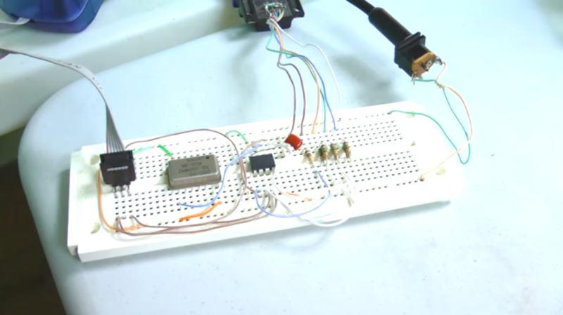
[lucas][RB] is using an ATtiny85, the larger of the ATtiny series of microcontrollers. After connecting the required clock signal to the microcontroller to get the 25.175 Mhz signal required by VGA, he was left with only four pins to handle the four-colors and stereo audio. This is accomplished essentially by sending audio out at a time when the VGA monitor wouldn’t be expecting a signal (and [lucas][Rad Brad] does a great job explaining this process on his project page). He programmed the video core in assembly which helps to optimize the program, and only used passive components aside from the clock and the microcontroller.
Be sure to check out the video after the break to see how a processor with only 512 bytes of RAM can output an image that would require over 40 KB. It’s a true testament to how far you can push these processors if you’re determined. We’ve also seen these chips do over-the-air NTSC, bluetooth, and even Ethernet.


er if it aint 320×200 256 colours its just not vga. you can do dithering below vga, but its not vga.
[Lucas’s] monitor thinks otherwise.
Well the VGA standard requires at least 320×200 256 … so its not VGA its RGBHV video
but i don’t blame anyone for calling it VGA
He’s actually driving it at 640×480 @60Hz. The bitmap maxes out at 170×240.
Okay, Red, Green, Blue, what’s the fourth in VGA? And where does the sync signal come from? (Sync on green perhaps?)
Otherwise, impressive work.
looks to me like its used for the clock
VGA has separate hsync and vsync lines.
He “cheats” by feeding combined-sync into hsync, and leaving vsync unattached.
What’s more impressive is combining audio with the red and blue lines. It’s a very clever concept, and worth reading the thread just for it.
I have never gotten a VGA monitor to work with composite sync. I wish I could lol it would save a lot of trouble.
In the schematic I saw he was driving both HSYNC and VSYNC and using diodes on the same two IOs to drive the color lines giving 3 colors plus black.
Oh, and for where composite sync does work – it goes to HSYNC and VSYNC is held high as the SYNC’s go into an XNOR gate.
I can see doing the audio in between horizontal sync, you get something like a 30KHz sample rate, depending on the vertical resolution. Would surely be choppy though, need a capacitor so smooth it out.
He’s splitting the two signals by polarity, audio is negative and video is positive. But how do you do that on an AT Tiny? Is there a virtual ground set somewhere in between? Video and audio are both within a range of about a volt, so there’s room to do it. But I don’t see a virtual ground anywhere.
Come to think of it, how does he do the bouncing ball? That impressed people on the Amiga. Although the Amiga’s CPU only ran at 8MHz, it had the luxury of real screen RAM to render into. Does this thing just buffer one line at a time?
Also just a guess, but did Brad do the new Atari-style joystick input with a load of resistors? Running into an ADC input, each joystick input shorting out a particular resistor. That’s been seen here before as a way of squeezing several switches into 1 MCU pin.
The I/O pins can be tristated too. So this is what I think:
– Video has far side 75 ohms termination. So drive ‘1’ to turn on pixel, tristate to turn off pixel. The black level isn’t at 0V, but determined by the 2 Schottky diode and the pull up as part of the divider.
– Audio has pull up and a cap for filtering. So drive ‘0’ to set output low, tristate to high. The drop from the pixel turning off is partially offset by the filter cap and the fact that audio low is higher amplitude than pixels leak. Yes there will be noise there.
Good call on that one.
Indeed, 75ohm internal termination plays a roll in the 3 state pins. Correct on the caps as well.
As for how I get so many free cycles per line, that will have to wait for the official release!
RadicalBrad
FYI: The rotating ball effect in the Amiga “Boing” demo was done by playing with the color look up table.
I wonder if it be easy to use three to create 8 colors per channel, and if so, would it be possible to increase the amount a chips and create a 640×480 output. Of course getting the timing right might be a pita I think.
Just use a larger chip with more SRAM. The bottleneck is usually the horizontal resolution as that depends on how fast you can toggle IO pins.
Horizontal res is *also* limited by how fast you can bit bang a pixel. It takes 4 clocks to do that, so that’s why horizontal res are 1/4 of the usual 640 + some overscan and not going to get you higher res. horizontally. Vertical res. is 1/2 of the 480, having more RAM can bump the vertical resolution as you are no longer painting the same line twice.
im very impressed! i was unaware you could even clock an 85 at that high of a speed!
Most of the ATtiny and ATmega’s can be overclocked quite a bit but you loose spec (especially the temperature range). Most of them can overclock a little way with the internal oscillator (used with an external crystal) but you can get much more overclocking from them by using an external oscillator.
In this project he used an external oscillator block. At 25.175MHz but I would expect that a crystal would have worked. It easier to find oscillator blocks for that frequency than normal crystals.
If it is specified as fundamental frequency (and not 3rd harmonic).
If you are doing breadboard, you are better off with oscillators anyways as breadboard is quite bad for analog circuits these frequencies.
44.24Mhz on an ATtiny13a.
http://nerdralph.blogspot.ca/2015/07/externally-clocking-and-overclocking.html
Who is [Lucas] ? His name is Brad, or [AtomicZombie] if you prefer…
Well, my DAI “Personal Computer” did this already in 1982 – with an old-fashioned 8080A (and a some-120-ICs graveyard), 48kB of RAM and with mere 2MHz clocking rate (officially, but DRAM access was limited to 1MHz, only 2kB of static RAM, mainly for system purposes were accessed in full speed) it brought up to 240 x 528 pixels in vivid 16 colors, not VGA, though. But I must admit, the DAI board was much bigger, much more chaotic and surely more energy-hungry than this one! Nice thing!
Bah! 680x1024x64 with 512B of ram, realtime-rendering, just not at VGA refresh-rates…
erm, no edit… rather 680×768
What aspect ratio is that? Got me baffled!
stretched across a 1024×768 display
bleh, it’s not really a relevant comparison; apples and oranges. This guy’s thing is VGA, this other thing is an old laptop LCD. This guy’s thing is 60Hz refresh, this other thing is nowhere near that.
Impressive work, Lucas!
So what’s the dot clock then, just out of curiosity. I am probably assuming that you chose the horizontal resolution to suite a clock frequency or was it that you chose the horizontal resolution to site the available SRAM?
Either way, your choice seem very interesting, any hints?
See my note above, and otherwise I’ll letcha search for “680×768 avr” and leave the remaining commentary-space, here, for that related to this project! My bad, Lucas, er Brad.
If you want anything vaguely close to the VGA standards your options are 640 x 400, 640 x 480, 800 x 600 or 1024 x 768. There are mangled versions for wide screen ratios but I’ve no idea where you got those numbers from.
you forgot 640×350
That’s EGA.
Mind blown. this is pushing the limits.
Agreed, by the laws of oneupmanship – I think he has won! No one can do better than that.
Oh, I dunno.
A guy on the #avr channel on freenode has an attiny85 generating text on VGA. One chip gets monochrome. Three chips synced gets you 8 colors. With 9600 bps bitbanged UART for comms for updating the data on screen. He even has the ability to scroll both vertically and horizontally. I’m trying to get him to put this all together in a nice blog post. He calls it the octapentavega.
I will look it up. But in the mean time [lucas] has the prise here. And I expect that, that wont change. You can get more out of more processors but that doesn’t necessarily beat what someone can get out of one processor.
That video is static,,,moving but static image. Same with the audio. Impressive on its own yes. How do you change the image? With the octapentaveega it is a fully dynamic functional terminal like display with vt100 like escape codes. I’ve watched the development of it fromthe start and I find it very impressive. He was hoping to get it done in time for the square inch contest but kept adding features. Hopefully we can get some kind of post up by christmas for it.
https://github.com/Jartza/octapentaveega
OctaPentaVeega 1 inch square vga board,,,with lots of stuff…check it out.
Well, I’m making the OctaPentaVeega and while I admit that Brad / AtomicZombie (not Lucas!) has made something very neat here, I also think OctaPentaVeega is neat in it’s own way – completely different approach with UART and ANSI-escapes.
And yeah, it’s not done yet, I thought it was but now I’m aiming for 32×16 characters on screen (meaning ALL of the 512 bytes of RAM used for screen buffer :))
//Jartza
Have to wonder why one wouldn’t just use a chip with more pins, rather than 3 8-pin ones paralleled together.
Where is the code?
Thanks for posting my project!
It has been fun making a 512 Byte Processor push VGA,
Just a few notes / comments…
I now have it doing 184 x 240, and it includes a joystick!
VGA is rendered to the 640×480 60Hz Standard mode.
Here is a video showing the joystick control…
https://www.youtube.com/watch?v=AjL2fFsBR48&feature=youtu.be
I have since changed to a standard Atari style joystick.
Also… Have never been called Lucas before! Many things, but not Lucas.
Cheers!
Radical Brad AKA AtomicZombie!
Doh!
Shame-faced editors failed to catch mistake. Fixed!
BTW, really really amazing bit of work.
Here is the Schematic. Joystick is a bit different now though…
http://www.avrfreaks.net/sites/default/files/Untitled-1_4.png
Cheers!
Radical Lucas… I mean Brad!
zoomxx.. the code you ask?
It’s in the micro-controllers Flash Memory, of course!
Brad
In the micro-controller I can find the hex. I am speaking of Source Code. I din’t see it. If I wish to replicate your results I need the sources.
Great results anyway!
Forgot to add…
The Specs on this Game System are as follows…
– 184 x 240 VGA draw over a 640×480 screen, following the EXACT standard.
– 8 colors – Black, White, Red, Green. Blue, Magenta, Yellow, Cyan
– 2 or 4 channel audio, sent as line level Stereo to any computer speaker set
– Sprites of any possible size, which include alpha pixels (transparent pixels)
– Joystick with Atari / C64 style connector and functionality
– Plenty of free cycle time to make games as good or better than VCS
I am working on several new games, and will post videos here later.
Cheers!
Radical Brad
I dare to say that is all fake. Your videos show 1990’s screen savers that’a all.
You will never show the AVR code for the pretended VGA on atTiny85 because it doesn’t exit.
The schematic in themself are nonsense. On the one the one above you even forgot that VGA require 2 sync signals HSYNC and VSYNC.
On the one shown on avrfreaks you send video and sync signal on same 2 wires with 2 diodes (D1,D2) to supposedly isolate the sync from the video but the way its done it isolate nothing. when PB0 and PB1 switch between 0V and 5V so does HSYNC and VSYNC.
Why would you bother faking something like that? This isn’t Youtube.
For the sync issue, isn’t sync often negative polarity? So diodes would split it effectively, as long as you’re generating negative signals. Which would require either a split power supply, which would be really weird, or a capacitor, which might affect the picture.
Then again, some monitors can use sync-on-green, sync pulses on the green video input. I dunno. Doesn’t seem likely guy’d just make it up then post here. That’d just be weird.
Let’s do some simple math: 184 horizontal pixels that must be serialized in less than 25.4µsec. Has per schematic above the attiny85 is running at 36Mhz. So the cpu instruction cycle is 27.8nsec. if the mcu send 184 pixels in 25.4µsec, the pixels must be sent at an interval of 25.4µsec/184= 138nsec.
Tcy=27.8nsec
Tpixel=138nsec
How many Tcy/pixel? 138nsec/27.8nsec=4,96Tcy/pixel (less than 5Tcy/pixel).
An MCU can’t do much processing in 5Tcy. If the bitmap was stored as a RAM byte array it would be enough shift out
byte but there is no RAM array. The image could be store in flash but there is only 8K flash…To store an 184x240x8colors (3bits needed per pixels) it required: 14.7Kb. Where the parrot image come from then?
In the videos the images are a fraction of screen size. This imply a shorter pixel period as the 184 pixels are not spread over 25,4µsec but a fraction of it.
for reference: http://www.javiervalcarce.eu/html/vga-signal-format-timming-specs-en.html
From this it shoud be obvious to anyone that is all fake.
My OctaPentaVeega pushes out 192 horizontal pixels from 20MHz Attiny85, not even overclocked. How about that?
//Jartza
Image can be compressed to fit it in 8KB. Decompress into RAM, one scanline at a time during background/blanking time.
@Arentz,
This means decompressing during each line during horizontal sync or 3.8µsec this is 136 Tcy. A simple compression algorithm like RLE maybe.
you miss 2 points:
1) The parrot image is about half width of screen. This means all the pixels are shifted out in less than 12µsec. or 12µsec/184/27.8nsec=2,3Tcy/pixel. impossible to shift the data to the port at 2 cycles per pixel. It need 2Tcy just ot read one byte from RAM to register. Then 1Tcy is need to push it to the port. Even by unrolling the loop it can be done. The unless the parrot is only 92pixels/width then rate doesn’t change is as calculate above (4,9Tcy/pixel).
2) the schematic above don’t make sense. There is single sync signal and VGA needs HSYNC and VSYNC. Furthermore the diodes don’t make sense neither. How can you believe it when just looking at the schematic says it is nonsense?
I stand to the my statement this is fake. One will never see the source code for this because it doesn’t exist.
Note that blue output is connected to MOSI, and green is connected to DO. Both can perform serialization. That only leaves red to do in software, with one bit per pixel that could be preloaded in 23 different registers.
@jartza42,
Your OctapentaVeega, is monochrome and use a shift register (USI) to output the video bits. No need for CPU cycle during the shift out. Old trick I did it many of my projects. Radical Rad can’t use this trick because there is 3 output bits.
Bonjour,
The inner loop has 5 cycles per pixel. Enough to bit-bang the outputs pins from memory.
The parrot image itself is 80 wide and 100 lines high. Needing only 3,000 bytes uncompressed, or more likely 4,000. The tiny85 has 8kB, so it should fit.
Since this post, I have even made the Video Engine do 316×240 VGA with 16 colors.
The video I posted (last one ion this page) with the SineWave Text was only 184×240 resolution.
Have been doing some fun 6502 + FPGA project lately, but will revisit this one again some day.
I did enjoy Jacques “must be impossible” comments though.
Posted the source code on AVRFreaks several months ago as well.
Cheers,
Radical Brad
Hey guys, there is no point arguing with Jacques!
He is thinking inside the box, and doesn’t get it.
Like I said, soon enough all will be revealed and there will be silence from the disbelievers.
…. as usual!
Went through the same thing when I claimed I could do 400×300 VGA with 256 colors and a GPU with ONLY 7400 logic components.
Some spend time preaching about why things can’t be done… others simply get things done!
Ok, last post. I am going to get this project completed now.
Ps… posted some code on AVRFreaks.
Cheers!
Radical Brad
Pretending getting things done is one thing really doing it is another. You never shown the schematic of your VGA built with logic gate (because obsiously it doesn’t exist). Same for this project (no code at all). And the schematic on this thread is a nonsense for 3 reasons:
1) VGA require 2 sync signals HSYNC et VSYNC not 1 as shown on this schematic.
2) the audio and video signals can’t be multiplexed on the same pins by just using diodes as shown on this schematic.
3) you pretend using the reset pin as joystick input. This implies that the reset function is disabled in the fuses and disabling the reset function implies using a high voltage programmer but as shown in your videos you use the AVRISP mkII which is a low voltage programmer.
As for my projects all information is available open source on https://github.com/picatout.
including my pong game on PIC10F322 (the smalless MCU running pong): https://github.com/Picatout/pong and video of it: https://www.youtube.com/watch?v=49pWwO0rc9Q
So anyone can replicate it.
Yeah, I have nothing better to do than fake projects and then post videos!
Like I said, all code and a complete tutorial is coming to my new site AVRCade.com soon.
The simple fact is Jack… I know a few tricks that you don’t. More than a few, actually.
You are acting like a Buffoon here, and trust me… I will come back to this thread and call you out once I have this documented and posted. No doubt, you will be very silent on that day.
Oh, and Jack…
Yes, you can use the ADC on the reset pin as long as it is held over 2.5v, hence the pull-up.
Rather than insulting others, perhaps you can unruffle your Peacock feathers and try to learn something new.
Au Revoir!
Radical Brad
I can’t wait to see your code on AVRCade.com. If it ever comes…
And I would also appreciate to see the schematic of your VGA made with logic gates. You certainly have a schematic of it, don’t you?
One of my other projects you call fake (Vulcan-74) is also a work in progress, so no, I do not have a complete schematic ready to publish yet. 24 pages of information detailing every step of the build with photos of progress and failures?… yes! But until the project is done, I am not making a schematic public…
http://forum.6502.org/viewtopic.php?f=4&t=3329
But Jack, take a few minutes to parse the link above and then ask yourself… “would someone REALLY do all of this work just to fake it”? What would be the point? I dare you to go on 6502.org and call my work fake!
I will take the high road and commend you on your Pong PIC game. It is nicely done.
But your shortsightedness on how I managed to utilize horizontal blanking is no reason to lash out.
In my Quark-85 system, I use the following timing…
// [36 MHZ HORIZONTAL CLOCK TIMING FOR VGA @ 640 X 480]
// HSP : 135 FROM 0000 TO 0134
// HBP : 067 FROM 0135 TO 0201
// HPX : 920 FROM 0202 TO 1121
// HFP : 022 FROM 1122 TO 1143
// TOT : 1144
And because of the way I render, I have almost 950 free cycles per line to pre-calculate and fill the 184 Byte Line Buffer used to draw each horizontal line. Add that to the fact that a line is also Auto-Erased during a draw, that leaves a LOT of free time.
Take some time and think about how this can be done, you will get it.
Some hints (since your a PIC guy)… LD=2Clk, OUT=1Clk, ST=1Clk. 920/5=184.
Oh, and here is another one for you to call fake. I generate NTSC fully in software on an XMega…
https://www.youtube.com/watch?v=CXFOTpM2Jn4
But let me guess our response… “no schematic, no real”!
I have been building these things for years so I can start the AVRCade site.
It will be a community of projects like these, and will even include yours if you can chill out, dude!
Have a splendid day Sir.
LOL, I’m starting to think that Jacques and Radical brad are one and the same.
@[Radical Brad]
I have looked at your vulcan-74 project several times. It’s awesome and every time I look at it I am tempted to go over to ebay and order a bulk lot of breadboards.
Fortunately (so far) common sense has prevailed and my sanity currently remains intact!
I would be very interested to see the schematic when your ready and if you release it and if the design is open source then I might try it or parts of it in VHDL.
For now I am fighting some self-defeating behaviours. I noticed that I bought lots of single conductor wire that is the perfect gauge for bread boards and also some wire strippers that can be pre set and they would also be terrific for breadboarding.
Oh those cute 14 /16 pin SSI/MSI DIP packages and I bet I can remember most of the pinouts to! They’re so cute.
No No help!
Hey Jacques…
Check it out, I grabbed a PIC10F322 and made it do color VGA….
http://www.avrfreaks.net/forum/quark-85-demo-kube-184-x-240-vga-8-colors-tiny85?page=6#comment-1810201
Just a simple Proof of Concept so far, but am working on a full game with sound and joystick now as well. This was my first attempt at PIC Assembly, but with so few instructions, it wasn’t too much of a learning curve.
The VGA Engine is the same one as my “Impossible” AVR version, just scaled to the PIC.
It is managing 60 x 60 VGA with 4 Colors, Mono Sound, and 3 Button Joystick.
Let me know if you want the HEX file to give it a whirl (AKA Proof!).
Hey Brad, the Future here looking back on your posts. Did you ever post the code?
It is great that you did something you enjoyed, but actually the only (O N L Y) reason it is interesting to most of the world is if they can learn from it. Just that you did it is nice. That you made some videos for show and tell is nice, too. But only for you. I see lots of people who were saying egregiously nice things about you trying to boost your ego and coax the code out of you, but it never happened. The thing is, most of them wouldn’t have even said hello if they didn’t think you were going to share the knowledge involved!
So looking back at your strong response to Jacques here, and the nasty things you said about him over on the avrfreaks forum, I have to say that it is exactly the same as if your project was fake! I believe you that your really did it, and yet, it is exactly the same as if it was fake. You talk about what a waste of time it would be to connect all those wires for nothing, what about the waste of time it would be to read about pretending to connect all those wires, and never actually get any information about it in the end? Is it mathematically distinguishable from being fake?
Could you maybe add a few more colours, using resistor splitters? Or would that take more time, and affect resolution?
While I find this very impressive, I don’t find this very usefull considering that in packing it into such a small chip, the optimization and cheats make it difficult to adapt. I’m still waiting for someone to put together a proper library/tutorial/circuit for getting a more capable arduino (like an uno) to do VGA, or even just color composite.
You can always just put my OctaPentaVeega shield on top of Arduino :D
//Jartza
No problem. I did it 2 years ago and posted the source.
https://www.hackster.io/janost/avr-videoblaster-8026fd
Thanks M.
I did this project for one purpose only… a personal challenge.
Since it was indeed challenging, I must therefore consider it “useful” as well!
On the flip side, I also made a VGA Game System with 200 Logic Chips…
http://hackaday.com/2015/08/11/vulcan-74-a-masterpiece-of-retro-engineering/
Also a personal challenge, so to me, so… very useful.
Anything that takes my gaze away from the TV to expand my mind… USEFUL!
Cheers!
RadicalBrad
Some people get demos, others don’t. We do.
We’ve got a lot of readers who’d love to peek at the source, and you could help a lot of others learn something if you shared it. Pretty please?
Absolutely!
Not only do I plan to offer the source for this one and the many others I have made, I am starting a website just dedicated to this kind of thing. Kind of a GIANT online book. Will also have a forum.
Just need to clean up the code a bit, make a few better games.
I also want to finish the Sound Generator on my massive 7400 logic system as well.
Once those are done, I will start documenting and posting code, schematics and tutorials.
I leaned all of this from the Online Community, so now I shall pay it back.
Cheers!
Radical Brad
Okay,
you answered here at my question.
Sorry Elliot, whatever Radical Brad says, no one will ever see source code for this. See my other comment on this thread. It is all boasting.
I love it! The greatest compliment for me is always disbelief!
Every VGA monitor can handle what’s called “Composite Sync”.
I will leave you to do your own research, as I have done mine.
Works on over a dozen monitors I tested in my Lab, old and new.
Do you think my other one is fake as well?…
http://hackaday.com/2015/08/11/vulcan-74-a-masterpiece-of-retro-engineering/
Anyhow, follow the AVRFreaks thread and all will be revealed when it is ready.
I wasn’t planning to release this until my new game is done.
Also cleaning up and commenting code right now.
I must now return to doing what I enjoy… CODING.
Later….
Radical Brad… (Moon Landing Believer)
I added a comment above with the math. The math tell the truth.
So jacques1956, is my OctaPentaVeega also a fake? :)
Must be. I will post some math truth to prove it.
Gotta love it!
Your OctaPentaVeega is monochrome and use a USI to shift out the bits. This doesn’t require CPU cycle. This an old trick everyone use. Radical rad can’t use this trick because he output 3 bits at a time.
Nothing to say now, Jacques?
That is much better than mine, although I did it a year ago…. :)
https://hackaday.io/project/8166-vga-signal-from-attiny85
Added a real Joystick to my project tonight…
https://www.youtube.com/watch?v=NzHm0gfZa1I
Audio / Video Engine is now complete.
Cheers!
Radical Brad
So if you went with black and white you’d only need one pin for the signal, and you would have some more breathing space, and might reach 16 levels, right? And that would make images more recognizable, albeit still boring due to the B&W (or amber/sepia if you add a resistor or two)
16 Shades of white would require 4 bits (Pins) for the color signal.
PWM from a single Pin would not work on the RGB lines, as it would be seen as a stream of bits.
Filtering to slow down the PWM would also not work, and just cause a smear.
But yeah…. it would be too boring anyhow! Games need color and sound!
Radical Brad
Start of an Omega Race like game.
Ship physics are ok, now need to add some Enemy Ships and ability to Fire Missiles.
75% of the Flash Memory still free, and plenty of free cycles for large Enemy Sprites.
https://www.youtube.com/watch?v=yXhaw3-3eWA
Cheers!
Radical Brad
https://www.youtube.com/watch?v=miefLPwZgOg
This is a seriously cool hack! I’ve been over to AVRfreaks and read the thread and the whole premise of this thing reeks so much of computing way back when – when an entire operating system AND application would fit in a 16 bit address space with room to spare!!
The fact that you’ve also got the video driving “hardware” running from the same chip, with 4.5 I/O… that is clever.
Jacques1956 may well be a disbeliever, and I can understand why. I am not an ATTiny dude (cut my teeth on Z80, then got into 8051 and more recently PIC), but from my reading of the thread a lot of work is done by the hardware peripherals of the chip with the software setting up timers and stuff.
For someone who knows assembler (and what it can do) and the intricacies of interrupts, the AVRfreaks thread makes an interesting read.
Nice work man!
Thanks for your comments.
In this one, the only peripherals used are the 2 timers. Everything else is bit banged, cycle counted, and optimized beyond sanity.
Timer number one triggers a horizontal line interrupt, and timer number 2 keeps track of the lost cycles from previous instructions executing before the ISR. Timer number 2 is used to “de-jitter” the AVR interrupts to keep an exact count on cycles.
Because of the recent acquisition by Microchip of AVR, I have decided to focus my next effort in doing something similar with the PIC line of controllers. Doing a a color PIC10F project similar to te ATTiny one shown here. From there, it will be PIC32MZ assembly.
Z80 was a good processor! Z80 and 6502… definite favorites!
Cheers!
Radical Brad
Radical_braid said:
“Posted the source code on AVRFreaks several months ago as well.”
Can you add a link please? Because I wasn’t able to find it among your post in AVRfreaks as AtomicZombie.
So how did this end, anyway? Love to see if it was all somebody faking it. I’ve seen plenty of bizarre and amazing stuff done with MCUs so I can’t say it’s impossible on any general principle. But in this specific case? He never put his money where his capable mouth was. Hm.
It ended in the usual manner, me moving on to other projects like this one…
lucidscience.com/temp/Quark-85.zip
And this one…
http://sleepingelephant.com/ipw-web/bulletin/bb/viewtopic.php?f=11&t=8790&sid=a547c741ff64976d05c30a1b747ad0b2&start=30
I also posted the source a while ago, but here it is again if you care for a look…
lucidscience.com/temp/Quark-85.zip
I added the Ball Demo in the User Code section as well.
As for Jack the dis-believer, he just simply failed to see how this was done.
I only drew every second scanline, using the blank one to setup the next line.
On the monitor, the blank line is much thinner than the live line due to the way the monitor draws, so the effect is what looks like a solid image with a bit of “retro” scanline look.
I am mainly into 6502 and VIC-20 these days!
… stepping back in time when computing was actually fun.
Cheers!
Radical Brad
Not sure how that link didn’t make it in my last post.
The other project I wanted to link to was this one…
https://hackaday.com/2015/08/11/vulcan-74-a-masterpiece-of-retro-engineering/
http://forum.6502.org/viewtopic.php?f=4&t=3329
Brad
I would like to dedicate this source code, schematic and greatly improved demo to Jacques1956…
http://www.avrfreaks.net/forum/impossible-graphics-power-atiny85
That’s 204 x 240 VGA @ 60 FPS with Alpha Aware Sprites and 4 Voice Sound coming out of a 5 pin Micro-controller with only 512 bytes of RAM.
Yes… 512 BYTES!
Cheers,
Radical Brad
Video…
https://www.youtube.com/watch?v=j8apFDjGUTQ