[Dannyelectronics] sometimes needs to measure tiny currents. Really tiny, like leakage currents through a capacitor. He’s built a few setups to make the measurements, but he also knew he’d sometimes want to take readings when he didn’t have his custom gear available. So he decided to see what he could do with an ordinary digital meter.
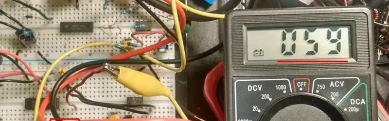
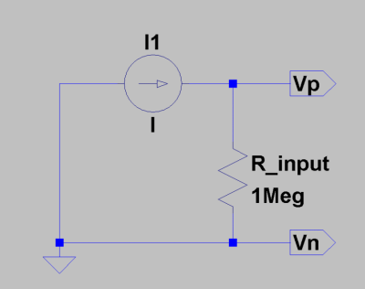 As you might expect, a common digital meter’s current scales aren’t usually up to measuring nano- or pico-amps. [Danny’s] approach was not to use the ammeter scale. Instead, he measures the voltage developed across the input impedance of the meter (which is usually very high, like one megaohm). If you know the input characteristics of the meter (or can calibrate against a known source), you can convert the voltage to a current.
For example, on a Fluke 115 meter, [Danny] found that he could read up to 60nA with a resolution of 0.01nA. A Viktor 81D could resolve down to 2.5pA–a minuscule current indeed.
We’ve looked at the difficulties involved in reading small currents before. If tiny currents aren’t your thing, maybe you’d like to try charging an iPhone with 3 KA, instead.


Quote: ” [Danny’s] approach was not to use the ammeter scale.”
Don’t you mean – ” [Danny’s] approach was not to use the voltmeter scale.”
Nope
Is this based on the assumption the input impedance is flat and accurate in the spec?
He’s measuring the DC leakage so it’s more about the simple DC input resistance than the complex AC input impedance.
The first stage in the meter is likely to be a op-amp that has reasonable DC like characteristics or a rather flat input *resistance*.
As for what the resistance would be … well you would have to measure it if you want any accuracy from this technique.
Anyone care to calculate the shot noise for 0.01 nA and the voltage noise caused by that across 1Mohm? Throw in the Johnson noise. I think the 0.01 nA increments is optimistic unless the integration time is pretty long.
I was under the impression that modern DVMs have a 10 megohm input impedance, and it’s pretty standard and consistent.
You can measure this quite easily with a 2nd meter: set the 1st meter to measure voltage, and use the 2nd meter to measure the resistance across the terminals of the first.
I was mostly wondering if was flat across the range. For what one usually uses a DVM for that won’t load the circuit too much is all you need to know, for this application to be accurate you’ve got to know as that is now the value of the shunt.
Nice, it’s always handy to be able to get around limitations like this.
On another note; I don’t think killing an iPhone with current via a couple of clamps to the outside, counts as ‘charging’ in any sense of the word.
Charged, sentenced and executed.
“Will it vaporize?” :-)
It’s the same GASP (Goldfish Attention Span Problem) issue with most modern “entertainment”: “don’t bother wondering what the question was, we get to blow something up!”
It works a bit different on multimeter costs more than $10. My Fluke multimeter:
– 200mV range has a direct connection from the input to the ADC via a 10M resistor (+ some additional resistance for the protection circuits). It *requires* an external shunt to work.
– 2V and up uses voltage divider with with switchable resistances in the auto ranging. Input resistance is the voltage divider network. The overall resolution will not as good as the 200mV. You’ll probably see a lot of voltage drops and the high resistance (10M+) will affect the measurement results.
The problem with the approach in the article is called burden voltage of the meter. The current flowing through the input impedance of the meter will cause a voltage drop (which is being measured) which will, however, also affect the circuit under test significantly, causing large measurement errors.
The proper solution for this problem if you don’t have a high-end bench meter is the Dave’s uCurrent:
http://eevblog.myshopify.com/products/ucurrent
It keeps the burden voltage tiny, because there is only a 10k shunt resistor (not a 1-10M input impedance of the meter) in series, so it will not affect your circuit.
The explanation of how it works and why do you need this sort of thing is here:
http://www.eevblog.com/files/uCurrentArticle.pdf
What this person is describing has nothing to do with Burden Voltage – he’s talking about measuring a current source through the high input of a DVM in Volts mode, which is about all you can do with this (see my post below). Burden Voltage is a term that only applies to a DVM when it is in Amperes mode. BTW, Burden Voltage is the voltage produced across a DVM’s internal current shut when it is in Amperes mode. Burden Voltage is named incorrectly. The burden units are strictly V/A (the voltage produced across the shunt for a given amount of current going through it). Units V/A equal Ohms, which is the resistance of the current shunt. So the strictly correct term is Burden Resistance, but the incorrect term Burden Voltage is now simply accepted as the historical norm.
I see someone else using one of the best multimeters ever made!!! <3 the Kelvin 50LE and related $2.75 models.
We need an article or video series called Five Dollar Lab, where every tool used must cost less than five dollars each. While the real wins would be new stuff that works OK for five bucks, I’d say that hints on where to find free obsolete equipment like easily-repairable scopes etc would qualify.
Hmm where do ‘free with a coupon’ Harbor Freight MultiMeters fall ? ;-) (Aside from the same drawer as the free 25″ tape measures and free Screwdriver sets…which are REALLY useful for making custom tools and handles for stuff, as well as the usual ‘Abused screwdriver used as prybar’ tasks.)
As someone who has worked in Metrology (measurement science) I can assure you that free 25′ tape measure will likely be quite a bit out. IOW-yes, virginia, even tape measures require calibration (the end result of which is a table of offsets).
I’ve seen tapes (the budget kind) up to INCHES out at 25′.
I bought a 30 cm ruler at the Dollar store.
Its 30 cm is 3 mm shorter than another plastic 30 cm ruler here at work.
“On today’s episode of “Dollar Store Hacker” we’ll tell you how to resurrect canned sardines with nothing than $5 dollars equipment and things you can find around your own kitchen!”
I do this regularly to measure current from a high voltage source. The <1 volt loss on the multimeter doesn't mean much when you're looking at 10's of thousands of volts. Plus with a big readable display and a battery, I can just let it float at 20KV and read it without having to get some device built with amazing isolation.
This approach is next to useless for practical current measurements. The only thing you can really measure is low value current sources, a pico trickle-charger for example. But that’s it. For-example, let’s say you want to measure the very small current consumed by a sleeping 3.3V micro-controller, knowing the DVM’s input resistance in Volts mode is useless, there is already 3.3V across the micro-controller – you can’t put the DVM in series with the micro-controller in Volts mode, that’s like putting a very high series resistance in series with Vcc, and the chip stops working.
I wouldn’t try measuring anything with a handheld Fluke DMM when the battery indicator is low. My old Fluke 77 started to measure high in these conditions after only indicating low battery for a couple of days. Imagine my shock to find a 9V battery measuring >12V.