If you’ve ever worked with FPGAs, you’ve dealt with the massive IDEs provided by the vendors. Xilinx’s ISE takes about 6 gigabytes, and Altera’s Quartus clocks in at over 10 gigs. That’s a lot of downloading proprietary software just to make an LED blink.
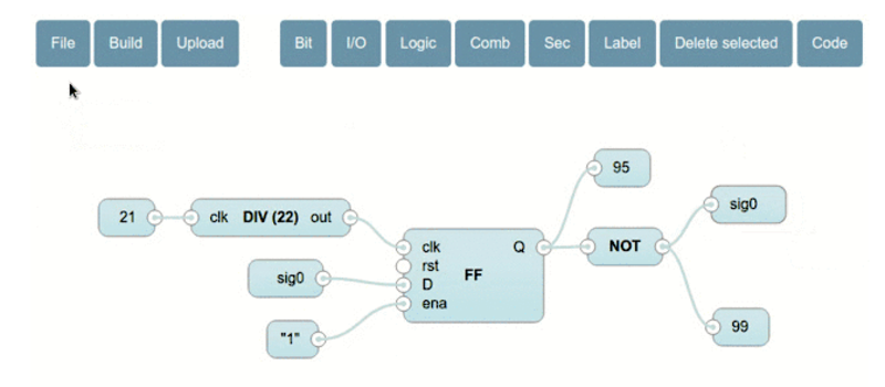
[Jesús Arroyo]’s Icestudio is a new, graphical tool that lets you generate Verilog code from block diagrams and run it on the Lattice Semi iCEstick development board. A drag and drop interface lets you connect IOs, logic gates, dividers, and other elements. Once your block diagram is ready, a single button press downloads the code to the iCEstick.
Under the hood, Icestudio uses IceStorm, which we’ve discussed on HaD in the past, including this great talk by [Clifford], Icestorm’s lead. For the GUI, Icestudio uses nw.js, which spits out JSON based on the block diagram. This JSON is converted into a Verilog file and a PCF file. The Verilog is used to create the logic on the FPGA, and the PCF is used to define the pin configuration for the device. Clicking on selected modules reveals the generated Verilog if you want to know what’s actually going on.
It’s experimental, but this looks like a neat way to get started on FPGAs without learning a new language or downloading many gigs of toolchains. We’re hoping Icestudio continues to grow into a useful tool for education and FPGA development. A demo follows after the break.
[Thanks to Nils for the tip!]
[Update: New Video!]


The Xilinx ISE allows Schematic entry for sadists Verilog for Mericans and VHDL for the rest of the word. Altera is the same.
I hope you don’t limit this to Verilog that is predominately used by Mericans or it will be a flop in the rest of the world.
The Icestorm backend (http://www.clifford.at/icestorm/) uses only verilog , but as it is an open source project has the potential to extend to more languages such as VHDL.
Yosys, the synthesis toolchain they recommend, actually supports VHDL files via translation to verilog.
as a n00b, i actually prefer Verilog… its so much easier to understand…
For me, VHDL is still a book with 7 seals.
If you are doing this professional, i dont think you will be using this toolchain anyway…
Its unfortunate that a lot of the world is locked into vhdl it is such an obtuse language.
There are advantages and disadvantages to both VHDL and Verilog, the subject has been debated and written about ad-infinitum. To root for one side over the other implies you don’t know both sides well. So unless you intend to parade your ignorance, don’t post Verilog vs. VHDL fanboy comments.
The synthesis backend, from what I can tell, already supports VHDL via conversion to Verilog internally.
The ICEstick is nowhere in stock, lead time 19 weeks, according to Xilinx.
Guess we’ll see each other again in July.
Icestorm backend is also compatible with the whole iCE40 family: http://www.clifford.at/icestorm/
Its not a Xilinx part
Its not in stock at Lattice, though. There are a number of alternative boards with the same FPGA, but I’m not sure of which ones you can buy, or the price. The “project icestorm” webpage lists a few variants: http://www.clifford.at/icestorm/
Instead of the stick for $20 with 1K gates, you can get the dev board for $40 with 8K gates. Both work with the whole IceStorm flow. More gates, more pinouts, more money. OTOH, in stock now at least at Mouser.
It’s more like $42+ $12 shipping to the USA… so bear that in mind.
iCEsticks are again available in 2023 post-pandemic, but they’ll cost you $50 or more. All FPGA’s have increased in price for many reasons. The modern IceStudio supports many development boards – consider carefully.
I think this is awesome. Not the graphical tool itself – I’m perfectly happy with verilog design entry – but the fact the open-source FPGA toolchain is catching up.
I only hope for better support from silicon manufacturers in future, but that’s probably too wild dream.
Look, I don’t want to belittle this or anything….any project that furthers open-source FPGA tool-chains is a very Good Thing as far as I’m concerned. In fact while we’re at it, props to Jack Gassett et al for the very good work they’ve been doing with DesignLab to try and develop a similar type of environment for the Spartan-based Papilio boards. But as far as I can tell all these projects do is generate VHDL/Verilog and piggy-back onto the horribly awkward proprietary frameworks provided by the manufacturers to get that code onto the silicon. A decent command-line tool-chain that is able to build and upload a VHDL led blinker in less than 10 seconds would be several orders of magnitude more useful than a pretty graphical drag-n-drop interface that pushes us yet another layer of abstraction further away from the slices.
Hi, there is also a little command-line toolchain called apio(https://github.com/bqlabs/apio) (based on platformio) that is been used by Icestudio. It is also experimental but it allows you to install easily all the toolchain (including scons for the build) with:
$ pip install apio
$ apio install
And then use “apio build” and “apio upload”.
Also, we are working to have this toolchain integrated with platformio (https://github.com/bqlabs/Platformio-FPGA).
According to my feeling the correct representation for electronics is a schematic with symbols for the logic gates, shift registers, etc.. It is the way I did my first and only FPGA. I am a HW engineer not a programmer. So for me VHDL is already very (too much) abstracted from the hardware. Of course I appreciate, what people can do with it.
You are not alone
Schematic entry is a cumbersome representation for FSM’s and other more abstract hardware. It also does not scale very well both in terms of complexity and development teams (more than 1 person work flows). Sure an HDL is overkill for making an LED blink, but a schematic is cumbersome when working with a real design like an ethernet MAC.
Anything to back these statements from a paradigm point of view? I’d say schematic entry and for that matter a visual programming language can be much better at describing a system that’s inherently concurrent.
As to working in teams…care to explain why not? Just because the tools aren’t there yet it doesn’t mean there’s something wrong with the idea of programming visually. Why do you need all the UML diagrams for describing your classes and FSMs?
Good point, but if we want to go down that route then the “correct representation” for digital electronics is mathematical (more specifically, combinational logic and FSM). In that respect HDLs are certainly more concise.
You need to click the links to IceStorm that were presented in the article. The toolchain is entirely free and open source. What’s presented here is the GUI tip of a very important iceberg. Click click! Watch [Clifford]’s talk.
The icestorm project (being called from GUI) doesn’t piggy-back to awkward proprietary framework and is able to build and upload verilog LED blinker in something like 10 seconds from command line.
Kewl and awesome!
Now, how long until we have arduino FPGA? ***ducks and runs for cover***
Working on it… https://github.com/bqlabs/icezum :)
An “FPGduino”? :-)
Like ZPUino (http://alvie.com/zpuino/)?
Check out the ZPUino. It might be just what you’re looking for.
IceStudio uses IceStorm which only works with Lattice ICE40 devices, no Xilinx, no Altera. The ICEStick at one time sold for $25+shipping but went the way of the Raspberry Pi Zero in stock.
(A side note, yesterday the local microcenter got a new shipment Pi Zero’s… All of ONE restocked. A miracle! It sold out in about an hour).
There is an ICE40 board on ebay for $70:
http://www.ebay.com/itm/LATTICE-SEMICONDUCTOR-ICE40HX1K-BLINK-EVN-KIT-EVAL-ICEBLINK40-HX1K-/252278433634?hash=item3abcf76762:g:g1UAAOSwvUlWtTC6
Too expensive, not worth it. If you want to experiment with FPGAs, get a $15 Altera Cyclone II board:
http://www.ebay.com/itm/1PCS-Altera-CycloneII-EP2C5T144-FPGA-Mini-Development-Board-/272086171657?hash=item3f59998009:g:pAgAAOSwZ1lWe-5v
Hopefully there will be more reverse engineering of the Xilinx and Altera bitstreams to support open source tools like this one.
Nice tool ! We have tried to push a web-based design tool with LOGI boards (LOGI-Pi and LOGI-Bone) :
http://valentfx.com/skeleton/
but very few people are using it for now. The main problem is that it generates Xilinx ISE project and VHDL files but cannot run synthesis because there is no open source tools to run synthesis for Xilinx FPGA.
I’m a fan of Verilog. Graphical design is perhaps easier to understand, but it’s less viewable.
There’s a missing step between the Verilog and putting it in the FPGA, though — the fitter. That in my opinion, is where the magic occurs: figuring out how to efficiently match the logic netlist defined by the Verilog code to the resources available in the device. It’s good to have the manufacturer’s help at this stage of the process.
I prefer to design using a Linux OS, but the big boys all write their development tools for Windows :-(
Xilinx have FPGA’s with ARM processors. It sure would be nice if they released a Linux based toolset that allowed you to compile and target your own processor. Self modifiable firmware, if you like.
Altera could do the same – but now they have been swallowed by Intel, they’d probably only do it with a Windows toolset.
Late to the discussion, but I just wanted to say that Xilinx, Lattice and Altera have all provided comprehensive Linux support for their development tools since at least 2008. I know this because I wrote a comprehensive Makefile-based build system for all three, targeting command-line Linux development.
I wanted to try this open source FPGA tool… but no chance. I can’t make it working.
My environment is MS Windows 10 with Python 2.7.15 with path correction. For now I don’t have any iCEstick connected.
When I try the example given in the video above, it says “build fail”.
I would assume that the installation was not correctly done and I would be happy about any advice on how to set up the environment.
Many thanks.
Does the iCEstudio support iCEblink40HX1K?
Thanks.
Can anybody help me figure out how they were able to convert there json to verilog file?
Thanks
Can anyone help me figure out how they were able to convert the json into a verilog file?