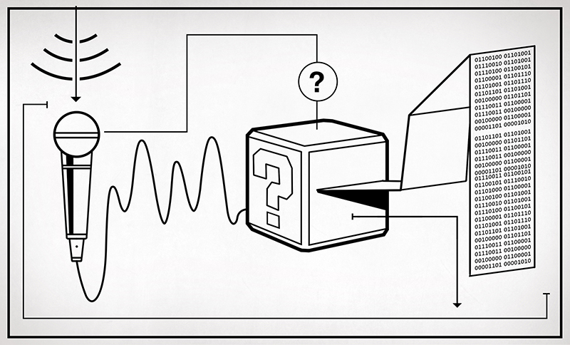
The physical world is analog and if we want to interface with it using a digital device there are conversions that need to be made. To do this we use an Analog to Digital Converter (ADC) for translating real world analog quantities into digital values. But we can’t just dump any analog signal into the input of an ADC, we need this analog signal to be a measurable voltage that’s clean and conditioned. Meaning we’ve removed all the noise and converted the measured value into a usable voltage.
Things That Just Work.
This is not new information, least of all to Hackaday readers. The important bit is that we rely on these systems daily and they need to work as advertised. A simple example are the headlights in my car that I turned on the first night I got in it 5 years ago and haven’t turned off since. This is not a daytime running lights system, the controller turns the lights on when it’s dark and leaves them off during the day. This application falls into the category of things that go largely unnoticed because simply put: They. Work. Every. Time. It’s not a jaw dropping example but it’s a well implemented use of an analog to digital conversion that’s practical and reliable.
Sensors and Transducers
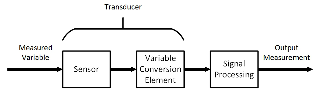
These might seem like synonyms, and they are sometimes used interchangeably but they are two different things. A measurement system is made up of three parts: a sensor, variable conversion element, and signal conditioning. The confusion between a sensor and a transducer is understandable since one of them includes the other, but not the other way around. A sensor is a device that measures a physical quantity and outputs a variable. The variable output from a sensor is not always a usable signal, which is the difference between a sensor and a transducer. A transducer measures a physical quantity (sensor) and converts the output variable to a usable signal. It’s kinda like the concept that every square is a rectangle but no rectangle is a square. Blink if you’re still with me, well, I’m moving on anyway.
Sensors
Sensors are used to directly measure the chosen input variable, in our headlight example the input variable is light intensity. The sensor used in this case would be a photocell. Let me curb some needless comments here and agree with you: yes, they are also called light dependent resistors, photoconductive photocells, and other names I’m sure. The way a photocell works is that the resistance across the cell changes over a set range with changes in light of a specific wavelength. Let’s have a closer look at what that means in a practical situation.


You can see from my demonstration photos that for the given photocell there is a resistance of 500 Ohm in a well lit environment and a resistance of 3.5M Ohm in a dark environment. Yes I am rounding the values to make nice round figures but for our purposes this is just fine, mainly because I decided it to be. If we were to design a measurement system using this photocell we would take some more detailed and specific data but we’ll assume our way through this fantasy build.
Transducers

I mentioned sensors and transducers were akin to squares and rectangles, some of you will complain about that analogy but I’m sticking with it. A transducer is the combination of a sensor and variable conversion elements. The sensor measures an input variable and often times the result is not as user friendly as we would like it to be. In our headlight example the changes in light intensity result in a varying resistance. Since we are working towards the input of an ADC we need this signal to be represented as a change in voltage rather than resistance.
One way this problem can be solved is by using a resistor bridge or Wheatstone bridge as it’s often referred to. By creating a pair of voltage dividers with a known supply voltage and well chosen resistors, we can control the output range of our bridge circuit. In our example circuit (Figure 2) we have the positive arm of the bridge on the left and the negative arm on the right. The positive arm is a voltage divider made up of the photocell (Rs) and resistor Ra. The negative arm voltage divider is a combination of a potentiometer (Rc) and the resistor Rb. In Figure 2 I included the potentiometer (Rc) as a real world representation of how I would build the ability to calibrate the bridge into the circuit, it isn’t otherwise used in our discussion.
Null Type Wheatstone Bridge
We will create a null type Wheatstone Bridge, which means that the output at the Vout terminals will be zero at the nominal resistance of the photocell. There is a null output (Vout=0) when Ra*Rc = Rb*Rs.
We can choose the nominal resistance to be any value within the range of the photocell (which is 500 Ohms to 3.5M Ohms). For simplicity sake let’s use a fictional photocell resistance value of 30K Ohm at dusk. To stick with nice round numbers we’ll run two tests. One using 1K Ohm resistors for Ra and Rb, the other using 100K Ohm resistors.
To illustrate the differences in those two resistance values I used Multisim to run a parameter sweep on Rs (which is R3 in the simulation) from 0 Ohms to 50K Ohms, which should give us a good idea of how this system will behave throughout the changes in light on a typical day. The Y-axis in the plot is the voltage at the output terminals (Vout) and the X-axis is the resistance of the sensor.


You can see that there is quite a significant difference in the behavior, the plot on the left using 1K Ohm resistance for Ra and Rb gives us an exponential response and on the right the 100K Ohm response is almost linear. This is good to know and implement one or the other as needed.
Signal Processing
So far we have a system that takes light intensity as an input variable through a sensor and the sensor outputs a resistance. Next a variable conversion element in the form of a Null Type Wheatstone Bridge takes the resistance and converts it into a usable voltage. The next step in the process is to take the signal that we converted from resistance to voltage and improve it. This bit changes depending on the situation, some sensors output changes that are so minute they need to be amplified to a voltage level that is easier to work with. Using an amplifier can improve the sensitivity and resolution.
Op-Amps
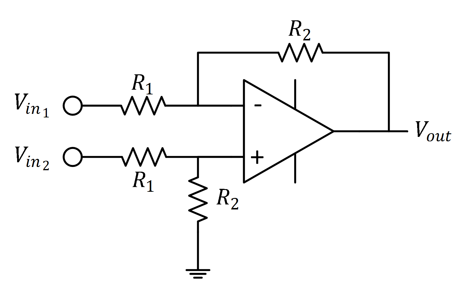
If we use the 100K Ohm model the output voltage range is from 2.7V at the brightest part of the day to -8.9V in complete darkness. Those are usable values that we could input into an ADC however we can remove the inductive noise that might be found in an automotive application using an op-amp.
We can use a differential op-amp circuit to suppress any signal that is common to both inputs Vin1 and Vin2 (in this case we’re supressing the noise). The resistors are labeled using only R1 and R2 to keep the math of this simple. In this configuration we can calculate the output voltage Vout = R2/R1*(V2-V1). We aren’t required to implement any gain in this situation so we can make this “unity gain” by letting R2=R1. If we did want a gain of say 100 then we would choose R2 to be 100K and R1 to be 1K, that is assuming the op-amp we used was capable of such a gain.
Last Thoughts
At the end of the day it doesn’t matter how powerful your ARM is or how cleverly you call your assembly subroutines, if you don’t understand how to build the analog front end your code won’t save you. This kinda goes hand in hand with Gerrit’s article about software and mechanical engineers. This analog stuff isn’t trivial, you can’t fix it with an OTA update. Now if we can get past all the sensor v. transducer arguing we have a pretty good plan laid out to measure light intensity with a voltage as the output. We removed some common mode noise by using a differential amplifier and if we want a gain we know how to achieve that as well.
Next Time
In the next installment we’ll go a little further down the path to having the analog signal converted to a digital value. We’ll have a look at some Instrumentation Amplifier examples and we might even have a look at an ADC.


This article was actually incredibly interesting for someone with only small amounts of experience like me. The idea of controlling the input so that it’s clean for interpretation makes a lot more sense. Thank you.
“If we did want a gain of say 100 then we would choose R2 to be 100K and R1 to be 1K, that is assuming the op-amp we used was capable of such a gain.”
Big mistake! If I had a pound for every time I’ve seen this ….
To simplify, consider that the inverting and non inverting inputs of the op-amp are at the same voltage – they have to be for an op-amp to work. You can now regard the impedance between the two inputs as zero. Therefore you’ve loaded the 30k photocell with 2k. Not good.
I had to discover all this knowledge first hand on my project to turn the analog voltage signals from my car’s sensors into digital information for a dashboard display. Looking forward to part II.
What is Vin1 and Vin2 on the op-amp?
The article did a poor job on this part–I think he’s intending that you connect the two Vout terminals in your wheatstone bridge to these. (+ to Vin2 and – to Vin1.) The assumption is that any noise in the line will be common to both sides of the bridge, and so the difference amplifier will remove that. But my problem with that idea is that so would any voltage measurement across the bridge–because you’re only measuring the difference between those two points anyway. So what exactly is the opamp getting you here? Or if he’s intending on tapping the 12V line itself capacitively to subtract only the noise, then you’ll need one of these on both sides of the bridge so both sides are “clean”. Then another difference amplifier may be needed to get a ground-referenced voltage for the ADC. I feel like I’m missing something here… which I almost certainly am, but that’s the whole point; the article doesn’t do a good job of explaining itself in this case.
The other issue, as addressed by Steve N above, is that the difference amplifier will put 2k in parallel with the 100k resistor in the bridge. This would be easily addressed by using opamps as voltage followers to buffer the bridge outputs with the difference amplifier inputs.
This article seems to be a great idea and tries to make the concept clear, but doesn’t quite live up to what I really need to understand it. That seems to be the case with nearly every tutorial style technical article I read these days…
Much was, indeed, a bit glanced-over… I can imagine it’s tough to write an overall article like this and decide exactly what level of detail to go into… different audiences need different levels of explanation. And the HaD crowd varies as broadly in experience-level as those building their first blinkies to RF-engineers…
As I understand, you’re spot-on about tying the output of the wheatstone bridge to the op-amp circuit. I actually need to think about it a bit to determine which goes to which… I guess if you think of the op-amp as a comparator, sheerly for the sake of figuring out which terminal goes to which, then a “comparator’s” output is positive when the + terminal is higher than the – terminal… So then, if you want the output of the *op-amp* to be *positive* when Vout+ is positive, then Vout+ should be connected to the + input of the op-amp (Vout+ -> Vin2), and Vout- should be connected to the – input of the op-amp (Vout- -> Vin1)… this is my thought-process, anyhow. Don’t think of the op-amp as a comparator for any other purpose than to figure out which terminal is which ;)
As I understand, the op-amp does two things, actually… As mentioned, it’s removing the “common-mode” voltage… that includes *both* the noise (as mentioned) AND the fact that Vout+ *with respect to* Ground is quite a bit different than Vout+ with respect to Vout-. So, e.g., say the output voltage (Vout+ – Vout-) = 2V… But the voltage Vout+ (to ground) = 7V, while Vout- (to ground) = 5V. Then the “common-mode” voltage is 5V (to ground), and that gets removed, once it reaches the op-amp’s output.
Then, say there’s briefly a spike of 0.1V of “noise” coupled onto the two wires (Vout+ and Vout-) with respect to ground, the difference between the two (Vout+ – Vout-) will still be 2V, but Vout+ will be 7.1V and Vout- will be 5.1V. The common-mode voltage (to ground) is then 5.1V, and that gets subtracted from the output. The noise is removed.
So, the output of the op-amp will output a voltage *with respect to ground* that represents the voltage *between* Vout+ and Vout-.
This is probably in consideration of the fact that most ADCs measure a single input voltage, with respect to ground. So, you *could* wire up two ADCs to Vout+ and Vout- and do the subtraction in software (assuming your ADC can take a 7.1V input!), or you could use this op-amp circuit to do the subtraction for you. The benefit, as well, being that those noise “spikes” may occur very briefly, and most microcontrollers with multiple ADCs can actually only sample *one* at a time. The first sample (Vout+) might measure the spike, but by the time of the second sample (Vout-), that spike may have disappeared, and now your system thinks it measured 2.1V instead of the 2V output by the wheatstone bridge.
You’re also spot-on about the effect of the op-amp’s resistors on the output of the wheatstone bridge. The general rule is 10-to-1 (I usually use 100-to-1, when I can)… As long as all the resistors on the wheatstone bridge are 100 times smaller than those on the op-amp circuit, you can somewhat reliably ignore the resistors on the op-amp circuit, but when they are closer in value than that, then you absolutely need to consider them.
Good call about voltage-followers.
RandomComment, you’re quite right, buffer both input legs of the differential amplifier with voltage followers and the problem goes away, although you are now introducing more amplifiers with their inherent temperature drifts. I’m pretty sure Analogue Devices make or used to make differential amps with the buffers built in – I think they were known as instrumentation amplifers. Whatever you do though, all the time you measure the output voltage of the bridge, you are still dependant upon the stability of the supply voltage.
One way round this is to have a huge gain on the differential amplifier (comparator really) and have something controlling the impedance of Rc in the bridge. A control loop adjusts Rc to keep the voltage output of the bridge at zero (nulled). The control value for Rc represents the photocel resistance.
I’m reminded of thermal transfer bridges I used to use a long, long time ago …..
Love it! Looking forward to part II
The Wheatstone bridge can go much father than this. I would balance the bridge with two photocells (a second one instead of Rb) to increase output. The output voltage would be an average of the photocell resistances. You would not include a potentiometer in the bridge. Pots have notoriously bad temp drift. The differential amp configuration does not provide an even input impedance which is bad with large source impedances. An instrumentation amp is almost universally used with Wheatstone bridges. Gain and offset should be corrected for after the inst amp.
the use of sensor and interface is wrong
According to my textbook from uni(and wiki) transducers turn one type of energy/physical property to another (fx a engine turning explosive force to torque force). Where a sensor is generally know to only “sense” part of the energy/property and turn it to a (most commonly) electric property as resistance, capacitance etc.. (sometime the interface part is also considered a part of the sensor)
The Wheatstone bridge part is know as a INTERFACE as it change the transducer’ “raw” output/signal to a voltage, current, frequency etc. that is desired
whoops meant the use of the word sensor and transducer
Thanks for pointing this out.
That really bugged me when reading the article. It appeared to me that “sensor” and “transducer” were swapped, according to my uderstanding of the terms, and I had to look it up to restore peace of mind.
The best is when textbooks make mistakes like these… IOW: All the time.
Cool “?” box, btw.
Absolutely. A transducer “transduces” a signal from one type to another. The transducer is a key part of a sensor system. The articles does a good job at confusing the reader in this regards.
Or you could hook your wheatstone bridge up to a $1.50 HX711 breakout board which does all the complicated signal crap on the same silicon that gives you a nice simple Arduino-friendly digital interface to read its 24-bit ADC.
Oh, wow, I always thought wheatstone bridges were heavily-reliant on the middle resistor… when you draw it this way it makes total sense, it’s just two voltage-dividers, one of which has a varying resistance.
I have a nagging sensor problem that I can’t seem to figure out.
The sensor is a resistive strip with a metal band over it, and touching the band to the strip acts as a potentiometer. The two ends of the resistive strip are connected to variable voltage sources, so you basically got a linear position sensor that outputs a voltage between A and B in the range from 0-5 V. The strip itself is on the order of 5 – 50 kOhm.
The output goes into the positive input of an op-amp configured into a comparator with a 1.5 nF positive feedback capacitor to get it to switch faster. The comparator produces a PWM signal for later purposes. The idea is that when the band is lifted off the strip, the signal goes away and the PWM immediately goes to zero.
Now, the problem is that when you touch the metal band, you get line hum through your finger, which is made worse by the fact that there’s (potentially) ungrounded computer PSUs in the loop giving you up to 110 volts and couple microamps of unwanted modulation on your fingertip. That’s the worst case scenario, and I need to figure out a way to make the circuit robust for line noise because it modulates the PWM duty cycle and causes problems downstream.
I’ve tried a passive twin-T notch filter between the op-amp and the strip, but the problem is that the positive feedback of the comparator charges up the capacitors in the notch filter and once you touch and release the band, it locks to about 50/50 duty cycle. Eliminating the feedback path, the filter works but it responds really slowly and it takes seconds for the signal voltage to wind down.
Ideally, I’d like to reverse the whole thing so that the metal band is connected to a voltage source, because that would be a low impedance path for the line noise, and use an op-amp to somehow measure the linear position and produce a voltage between A and B, and 0V if the metal band is off the strip.
If the metal strip is simply a variable voltage input for your comparator then I’d try a simple resistor-capacitor low pass filter to damp out any AC being picked up. If that causes interference with the comparator then perhaps an OPamp buffer between the sensor and the comparator with low pass in the feedback loop
The thing is, a lowpass filter that attenuates 50 Hz to any reasonable amount causes a huge delay in the signal where it takes several seconds for the voltage to settle fully.
I’ve now changed the circuit to: (input) -> (1.5 M pulldown) -> (buffer) -> (notch) -> (comparator) and got rid of the self-oscillation issue by the fact that the buffer pulls the voltage to zero without input, but the settling time issue still persists.
The pulldown is a bit of a problem a well because it introduces non-linearity by drawing some small amount of current through the potentiometer. For example, you can approximate a logaritmic pot with a linear one by using a 1/5R pulldown on the wiper.
Is the metal band insulated on the topside? The worst case would be if not. Touching the metal band induces huge amounts of line hum. If it has an insulaion then the coupling is capacitive only. In this case I would try to make the insulation thicker (like plastic film or sheet or a layer of silicone rubber) to reduce capacitance.
15 volts and 20 microamps to be exact. I measured it with a bare foot on the floor.
The thing is, the metal band bends and stretches as it’s being fingered, so any lamination on top will eventually peel or scrape off.
I’ve now managed to move the metal band on the supply side by using a current mirror to draw a pre-determined amount of current through the strip. The band is now connected to the output of an op-amp buffer that acts as an ideal voltage source, so it sucks up the line hum as it attempts to maintain steady voltage. Touching the band to the strip sinks the set current through the resistance and together with the mirror transistor forms a voltage divider with a total voltage drop equal to the input voltage. The output is then simply the voltage drop across the transistor. When the finger is lifted, the transistor pulls the output voltage nearly to zero.
Here’s a link to the falstad simulator:
http://pastebin.com/z7mZFYQT
It has good linearity between the input voltage and one diode drop (~600mV) and that’s good enough. Making the current setting resistor on the input leg of the current mirror equal in value to the resistive strip means that the voltage never drops to the non-linear region, and differences in gains of the transistors seem to be inconsequential.
Now the remaining issue is in how to shift the output voltage range to an arbitrary DC offset, and still return back to zero when the finger is lifted, preferably using the output buffer op-amp to do it because I have a dual op-amp chip.
Interesting & valid comments all! Now as an instrumentation/automation guy for 3 decades may I suggest looking a little farther than transducer vs. sensor. In my field something must be measured in order to manage or control it. So where as rhe sensor/transducer measures a ‘physical parameter’ the resultant signal (analog or digital) is transmitted to a ‘controller’ (PID, on/off, Arduino etc.) where it is processed/interpreted & a proportional, measured & controlled signal is forwarded to the ‘final control element’ whatever that may be to successfully complete the operation be it a one time thing (batch) or an on-going continuous situation. Now I have not mentioned any of the things alluded to earlier here such as measurement uncertainty, signal integrity, SIL or ‘what if’ type factors. Hope I have not bored you but instead assisted by giving another perspective. Thank you all for your insights & thoughts
Any document titled “Instrumentation Essentials” — particularly on the introductory section — should use the words: impedance, responsitivity, bandwidth…. Later sections should delve into noise and errors. The entire purpose of instrumentation engineering is to take quantitative measurements with known errors.
For those with no knowledge of instrumentation engineering or AFE, this page over simplifies the topic as outlined in above posts. Those interested in the field should read some of the old app notes from Linear and TI.
Sensor – a thing that detects and responds to a phenomenon. no “conversion” required! The rise of hot, expanding mercury is a sensor, sensing the heat applied to the bulb. This is a “heat to heat” sensor. The first mechanical wind sensor was the hanging signboard outside of a tavern. Force to Force. A pittot tube senses wind force through the entrance and uses it to force water up the tube. Force for Force.
Transducer – responds to one phenomenon by exerting another. What do you mean by “variable conversion elements” ?!? Many sensors have non-active or non-electronic “variable conversion elements”. Most commonly, we use some electrical property as one side of our conversion. Force of air blowing on the microphone element pushes the diaphragm in and out, where by magnet interacting with coil produces a small current. The amplifier attached is secondary, and not technically the transducer. It is the transducer amplifier. The transducer is a kind of sensor. The exact opposite process on nearly identical mechanism is called a speaker.
But transducers do not need to work with electrical properties. Another type of temperature sensor exchanges the heat to mechanical force. A bi-metal laminate bends when it expands due to heat, because one metal expands faster than the other, forcing the metal strip to curl. This mechanical force rotates the gauge.
Figure 1, while esoterically correct, confounds the understanding. The diaphragm of a microphone is the sensor, and the magnet and coil the “variable conversion element”, but it serves no purpose to think of it that way. Transducer. Done. Breaking it down allows for the assumption that transducers have some sort of intelligence in them.. some ADDED parts, when in fact many/(most?) do not. Your LDR is a transducer. It converts light struck onto it into a change of resistance. But it is just a pattern of wire on a substrate. The “variable conversion element” is some chemistry of the wire pattern. But in this case, the sensor and variable conversion element are not two separate things (as in the case of microphone). They are one.
Also, I think the article pretty much missed the boat as far as explaining why one might use a Wheatstone with an LDR rather than simply a voltage divider.
LDR plus bias resistor gives perfectly acceptable ADC inputs, without ever going negative. “Darker than dark” does not exist as far as the LDR is concerned. Being a resistance element, the minimum theoretical resistance is zero, and going positive from there. If your automotive sensor goes into a processor of some kind, it likely does NOT use a Wheatstone, or even an op-amp.
Wheatstones are well suited for devices which have a resting bias in the middle of it’s range. A strain gauge is an excellent use case of a Wheatstone, since they rest flat, at the center of their resistivity. When bent inwards (compression), resistance goes low, and when bent outwards (tension), resistance goes high. The output of this resistance needs to be center balanced, and thus could be either positive or negative voltage. Thus the need for the wheatstone bridge. Even so, it will need to be conditioned and biased up such that the full range becomes 0 to ADCref.
An LDR on the other does not respond to a darkness level below a certain threshold, and only goes positive in resistance from there. So, in most ADC applications, a simple voltage divider will do. Possibly followed by opamp or other signal conditioning. But generally easy to interface.
Where I think this article failed is by not mentioning that the LDR/Wheatstone has a special application. The light level at which we choose a matching resistor for the LDR becomes our “zero point” and is thus a calibration for when we want the LDR to go positive. We can adjust the output of the Wheatstone such that it goes positive at dusk light levels. But this means that full noon brightness would give a strong negative value. Following up with an opamp and transistor or voltage comparator would allow us to effectively ignore negative voltages from the Wheatstone, and we are left with a simple switch that turns on at dusk light level.
But the configuration is not terribly practical for an ADC input. Which is what I think your car light system actually uses.
Consider the non-microcontroller solution: Lights turning on anytime the light level goes below the setpoint, and off when it goes above. Cloudy days, under bridges, passing cars.. lots of things causing temporary variability in the light level measured, and your headlamps flashing on and off seemingly at random.
No. More likely, there is at least some microcontroller and code in the background, filtering out these things. These days, it likely knows the actual time of day, due to CAN-BUS and the clock radio.
So long I didn’t read past the first line.
Your point?
I for one am happy that knowledgable persons post detailed information that is related to the article. Half the reason I come to HAD is to see some real input in the comments on what an article may have missed.
I think his point was that no-one reads all this crap 2 or 3 days after the article is posted, so it is best to spend your time on something else.
One might read that and think I implied that strain gauges can produce a “negative resistance”. obviously not the case. But how I wrote it could be confusing to newbs.
A 500 ohm strain gauge rests at 500 ohms, and its resistance goes up or down depending on the direction it is bent. The theoretical minimum resistance is still zero, and going positive. Though in practice, it would have broken long before then.
So, using an LDR with a Wheatstone only makes sense if you want some central resistance of the LDR to mean something. As in “I want the ‘resting point’ of this LDR to be at ?? lux, and to give me negative voltage below that lux, and positive voltage above it.”
I would call the rising mercury a heat to position or hat to length sensor and the hanging signboard also as a windforce/-speed to position or angle sensor. Also the pitot tube: water is forced up the tube to give a readable length/position indication.
Analog Devices Inc have a good introductory text (which is only tangentially a sales reference) available for download at http://www.analog.com/library/analogDialogue/archives/39-05/op_amp_applications_handbook.html . I found this a good enough read that I ended up buying a hardcopy of it.
For the next step along, http://www.dspguide.com is good too (I also ended up buying hard copies).
Beyond that, there are a bunch of good technotes floating around from TI and LT.
My particular area of interest comes down to the oft-overlooked issue of the antialiasing filters, and how to optimally choose them assuming you want to analyse in the time domain. (use either a Bessel or “linear phase” filter, and for heaven’s sake give your self a nice wide guardband between your AAF’s -3dB design point and your ADC’s 1/2 fs – don’t just set them to be the same! )
Your accuracy / noise floor will end up being whatever your AAF attenuates to, at 1/2 fs, so if you use a AAF set to half your sample rate, then you’ll have an “analogue to digital” converter good for a reliable SNR of just -3dB. It might seem to give better sometimes (especially in a nice, noise-free electronics lab), but as soon as some noisy source, like a triac dimmer switch, is turned on in the same room, you’ll suffer many annoying glitches.
ADI have a technote to the same effect, but it’s staggering just how many “DAQ” systems get this badly wrong – even from companies who one might expect to know better!
In some cases, the difference between a cheap ADC and a “good” ADC is just that the “good” one directs you to install a AAF with a decent guardband on the inputs, whilst not saying that’s what it is! (ie, “use these component values…”)
The other point is that your “temporal” precision isn’t your sample delay – it’s the width of the impulse response of your AAF/ADC combination, which – at best – is something like a single, narrow, blip. (Rather than a bump followed by a lot of ringing, which you WILL have if you try to use a narrower guardband by using a filter alignment that rolls off faster, or, possibly worse, a time-symmetric “sinc” shape in the time domain, which is often exactly what most computer sound cards do, because they’ve been post-filtered with a digital FIR filter set to have a “brick wall” frequency response.
I’ve yet to see a commercially-available DAQ system that properly specifies this in conjunction with it’s other parameters like “Effective number of bits” or SNR (same thing really). Perhaps it’s because it makes the bandwidth relative to the data rate look miserable?
Many many DAQ system seem to omit the AAF entirely – and there are firms which specialise just in just such filters. (although paying a $1000/channel premium to make the problem go away does come as a nasty shock).
What the other guys said Re: Transducers and why bridge.
Also: Analog Devices Inc have a good introductory text (which is only tangentially a sales reference) available for download at http://www.analog.com/library/analogDialogue/archives/39-05/op_amp_applications_handbook.html . I found this a good enough read that I ended up buying a hardcopy of it.
For the next step along, http://www.dspguide.com is good too (I also ended up buying hard copies).
Beyond that, there are a bunch of good technotes floating around from TI and LT.
My particular area of interest comes down to the oft-overlooked issue of the antialiasing filters, and how to optimally choose them assuming you want to analyse in the time domain. (use either a Bessel or “linear phase” filter, and for heaven’s sake give your self a nice wide guardband between your AAF’s -3dB design point and your ADC’s 1/2 fs – don’t just set them to be the same! )
Your accuracy / noise floor will end up being whatever your AAF attenuates to, at 1/2 fs, so if you use a AAF set to half your sample rate, then you’ll have an “analogue to digital” converter good for a reliable SNR of just -3dB. It might seem to give better sometimes (especially in a nice, noise-free electronics lab), but as soon as some noisy source, like a triac dimmer switch, is turned on in the same room, you’ll suffer many annoying glitches.
ADI have a technote to the same effect, but it’s staggering just how many “DAQ” systems get this badly wrong – even from companies who one might expect to know better!
In some cases, the difference between a cheap ADC and a “good” ADC is just that the “good” one directs you to install a AAF with a decent guardband on the inputs, whilst not saying that’s what it is! (ie, “use these component values…”)
The other point is that your “temporal” precision isn’t your sample delay – it’s the width of the impulse response of your AAF/ADC combination, which – at best – is something like a single, narrow, blip. (Rather than a bump followed by a lot of ringing, which you WILL have if you try to use a narrower guardband by using a filter alignment that rolls off faster, or, possibly worse, a time-symmetric “sinc” shape in the time domain, which is often exactly what most computer sound cards do, because they’ve been post-filtered with a digital FIR filter set to have a “brick wall” frequency response.
I’ve yet to see a commercially-available DAQ system that properly specifies this in conjunction with it’s other parameters like “Effective number of bits” or SNR (same thing really). Perhaps it’s because it makes the bandwidth relative to the data rate look miserable?
Many many DAQ system seem to omit the AAF entirely – and there are firms which specialise just in just such filters. (although paying a $1000/channel premium to make the problem go away does come as a nasty shock).
The world is not analog. The world has continuously varying, measurable, phenomena that can be transformed into an analog voltage or current. Temperature or sound or light can produce an analog signal, but temperature, sound and light are real phenomena and not usually an analog of something else. Please excuse me for being so pedantic – anyone reading the article will not be confused about this. Calling the world “analog” may be a useful shorthand but can be confusing to some. I have found some non-technical people who believe that the sound going into the microphone is analog and everything else is ‘digital’. ‘Analog’ is what follows the microphone and precedes the ADC.