Getting back to basics is a great way to teach yourself about a technology. We see it all the time with computers built from NAND gates or even discrete transistors. It’s the same for radio – stripping it back to the 19th century can really let you own the technology. But if an old-school wireless setup still needs a 21st-century twist to light your fire, try this spark gap transmitter and coherer receiver with a Beagle Bone Morse decoder.
At its heart, a spark gap transmitter is just a broadband RF noise generator, and as such is pretty illegal to operate these days. [Ashish Derhgawen]’s version, which lacks an LC tuning circuit, would be especially obnoxious if it had an antenna. But even without one, the 100% electromechanical transmitter is good for a couple of feet – more than enough for experimentation without incurring the wrath of local hams.
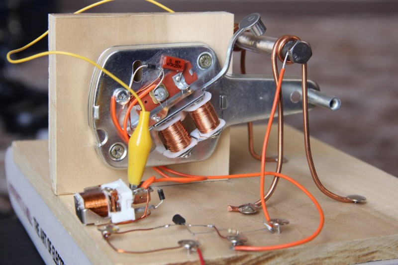
The receiver is based on a coherer, a device that conducts electricity only when a passing radio wave disturbs it. [Ashish]’s coherer is a slug of iron filings between two bolts in a plastic tube. To reset the coherer, [Ashish] added a decoherer built from an electromagnetic doorbell ringer to tap the tube and jostle the filings back into the nonconductive state. He also added an optoisolator to condition the receiver’s output for an IO pin on the Beagle, and a Python script to decode the incoming Morse. You can see it in action in the video below.
If this build looks familiar, it’s because we’ve covered [Ashish]’s efforts before. But this project keeps evolving, and it’s nice to see where he’s taken it and what he’s learned – like that MOSFETs don’t like inductive kickback much.


Interesting and excellent project.
I never would have guessed that an optoisolator could act like that! Simply amazing.
I doubt the opto led is actually lighting up. The is probably getting straight into the IO pin and it would work with just a piece of wire an no opto
I was suspecting that. However, when I removed the optoisolator from the Beaglebone (and just connected a wire to the GPIO pin), it did not work. It seems that the optoisolator is playing a role here. I”m guessing the diode in the optoisolator (the LED) is rectifying the RF signal (just like they do in crystal radio’s). Let me know if there could be another explanation as to why this is happening.
If you look at the 4N33, the base of the darlington pair is brought out to a pin. This pin is left necessarily floating, but a darlington pair has typically a ~10,000 gain, so even a small current on this floating base will result in the pair amplifying a current. The bias transistor will have 3.3ma of current flow through it when fully triggered. My experience with 3.3v logic is that it has a ~2.7v input trigger threshold, so you’re looking at about 2.7ma flowing through the darlington to trigger the BBB. If my math is right, it would take about 270na of stray current to trigger the darlington of the optoisolator without a current being present on the LED.
You could probably replicate the results with a TIP120 wired up the same, with the base pin floating. If you are using a breadboard, the grid tie it is connected to would act as an antenna.
BTW, didn’t I read about this last week on HaD?
That’s an excellent explanation, and I think you’re right. Sticking a wire antenna to the base pin should make it even more sensitive. I’ll have to try it with a TIP120,
maybe short the LED leads and test again?
I shorted the LED leads, and it still worked. So, it seems Perry is right
@Perry I have mentioned your comment in my blog post!