We have talked about a whole slew of logic and interconnect technologies including TTL, CMOS and assorted low voltage versions. All of these technologies have in common the fact that they are single-ended, i.e. the signal is measured as a “high” or “low” level above ground.
This is great for simple uses. But when you start talking about speed, distance, or both, the single ended solutions don’t look so good. To step in and carry the torch we have Differential Signalling. This is the “DS” in LVDS, just one of the common standards throughout industry. Let’s take a look at how differential signaling is different from single ended, and what that means for engineers and for users.
Single Ended


Collectively, standards like TTL, CMOS, and LVTTL are known as Single Ended technologies and they have in common some undesirable attributes, namely that ground noise directly affects the noise margin (the budget for how much noise is tolerable) as well as any induced noise measured to ground directly adds to the overall noise as well.
By making the voltage swing to greater voltages we can make the noise look smaller in proportion but at the expense of speed as it takes more time to make larger voltage swings, especially with the kind of capacitance and inductance we sometimes see.
Differential
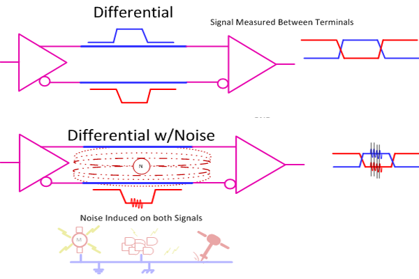
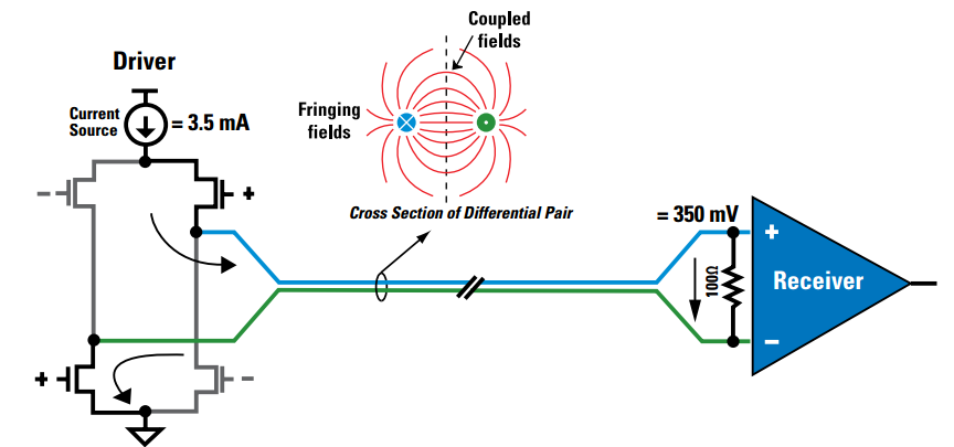
Enter Differential Signaling where we use two conductor instead of one. A differential transmitter produces an inverted version of the signal and a non-inverted version and we measure the desired signal strictly between the two instead of to ground. Now ground noise doesn’t count (mostly) and noise induced onto both signal lines gets canceled as we only amplify the difference between the two, we do not amplify anything that is in common such as the noise.
LVDS, CML, and LVPECL
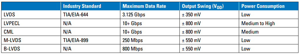
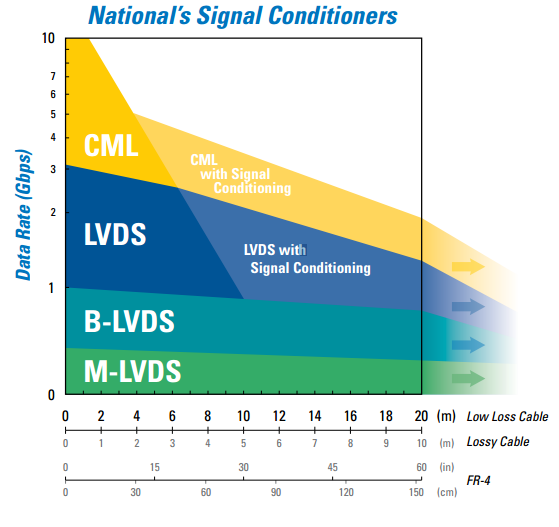
There are various standards with the more common ones being Low Voltage Differential Signaling EIA/TIA-644 (LVDS), Current Mode Logic (CML) and Low Voltage Positive Emitter Coupled Logic (LVPECL). Other examples of Differential Signaling in general include the older RS-422/485 which was used to extend the range of the common single ended signaling known as RS-232, (the “standard” serial port).
LVDS is also used in Serial ATA (SATA), Firewire, gigabit Ethernet and PCIe as well as often being used to communicate to LCD panels. CML is the underlying technology of HDMI and uses current flow instead of voltage as the name implies.
A quick way to demonstrate an LVDS signal is to utilize the fact that the outputs of many FPGA’s and CPLD’s are programmable as to the type of interface standard.
CPLD/FPGA as a Demo
First we create a quick counter right off of the 25Mhz master clock, I used a schematic entry for the top level:
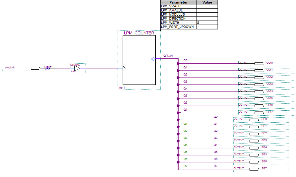
I created lots of different outputs to give myself options while making the video but ultimately just used a clocked version of the 25Mhz.
Next we go to the Assignment Editor for the part and simply select LVDS as the pin type. By selecting one pin it automatically assigns the pair to complete the Differential path.
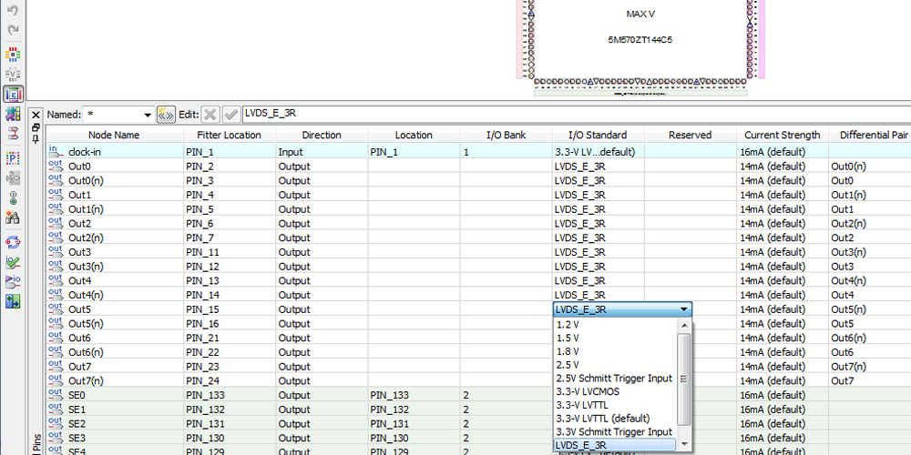 In this CPLD there is really just one differential standard to select (LVDS complete). Other CPLDs/FPGAs may have a wider selection and may require the use of external resistors or other components depending on the device and selected standard. They may also require the use of the same standard in a block of pins or along one whole side of the part.
The Schematic
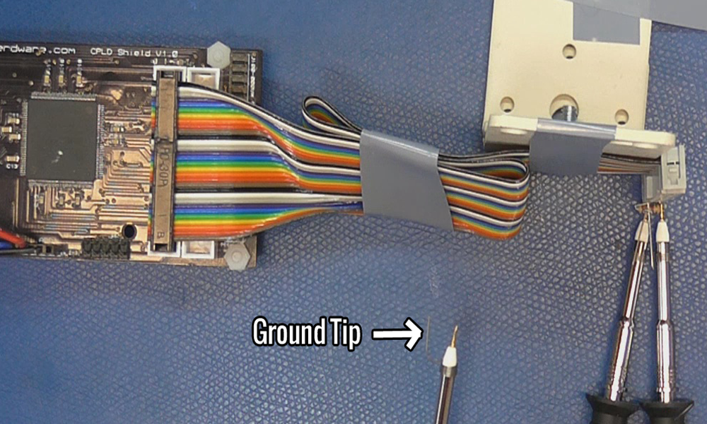
 Shown here is the PCB schematic showing the pin assignment with the insert showing the ribbon cable pin-out for differential signals. Note the ground connections interspersed between differential pairs on the 30 pin ribbon cable connector.
LVDS
The LVDS standard is to develop 350mv across the resistor at the end of the path known as the termination resistor. This value is chosen to best match the impedance of the signal path, with values between 100-120 Ohms typical for cables and PCB layout. As speeds go up we get real serious about calculating and controlling the impedance throughout the entire path.
 On the example on the workbench shown here there is no receiver, just the termination resistor. At these speeds and in this type of application it is best to dispense with a long ground lead on the scope probe, the slid-on ground clip is shown here instead.
Scoping It
Using the oscilloscope’s built in math function I can simulate what happens in a differential receiver by subtracting one signal from another. Anything common to both, sometimes called common mode noise or a common mode component, is canceled out by this subtraction. In the case where radiated noise is impinged upon both conductors equally , the noise cancellation works well. To this end, techniques such as twisting the cable conductors is common, with the more twists per inch offering better noise reduction but with increased cost, weight, and reduction in flexibility.
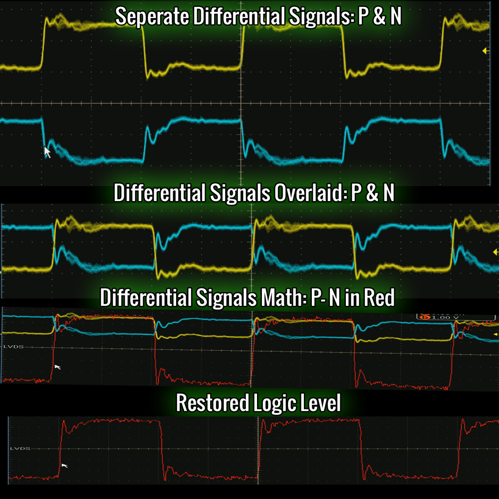
Seen here the individual traces are shown and then overlaid, and then the difference taken, with the final reconstructed waveform in red.
Some Standards
Bear in mind that we are talking about just the physical signaling here and does not cover encoding scheme where transitions are minimized, or the clock and signaling is embedded in the data flow.
To optimize high speed performance or to assist in converting from one standard to another, DC blocking may be employed through use of capacitors in series with the data stream. DC blocking also allows the receiver to operate right in the DC bias area that is best for it to reduce noise and things like “jitter” which is a variable delay in the signal.
AC Decoupling
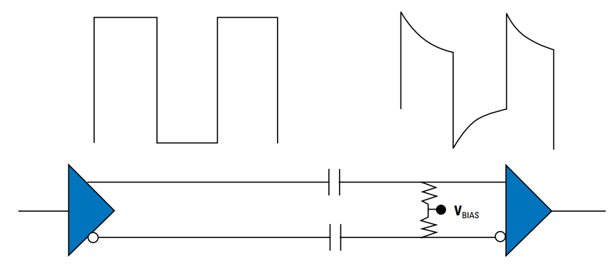
Removing the DC component, i.e. AC coupling the signal, comes at a price however. AC coupling requires that the signal always be seen as in motion or making transitions on a regular basis.
In the case of an encoding scheme that represents a logical “1” by a transition of the signal and a “0” by no transition, AC coupling then requires that a minimum of transition occur every so often so that the DC baseline of the signal doesn’t drift off. Without AC transitions coupling through the series capacitors driving the input fro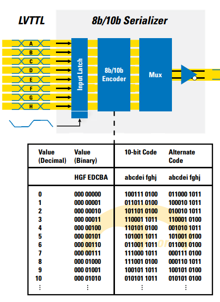 m a high to a low, the voltage would decay and drift towards a unusable value.
Encoding
An 8b/10b encoding scheme uses 10 bit symbols to represent 8 bits of data while “stuffing” some transitions into the flow so that too much time doesn’t pass without a transition. Telco’s have been using the schemes for many years for sending information over long distances of twisted pair wire using differential signals.
Off the Shelf
There is wide range of discrete drivers and receivers in the various technologies and as you would expect, the vendors’ web pages provide excellent product selection tools. In the old days we had to read or at least glance at every databook on the subject at least once and then narrow down the search by carefully digesting the specifications. Here is TI’s excellent selector that also includes what used to be National Semi:
Conclusion
As you would expect in this day there is a large amount of data available on the Internet. One of my favorites is the LVDS Owner’s Manual which is available from many vendors. I keep a printed copy of this in my lab.
Hopefully this starts to put a tool in your toolbox: If you need to go fast, far or through a noisy environment then consider Differential Signaling.


Good article, thank-you
Thank you I just spent my day yesterday reading about this.
Great article. Differential or balanced signaling extends the range of copper pair communications to amazing lengths. I’ve used 422 4 wire to control equipment over 2 miles away over copper. When error correction is added to the natural noise resistance of this method it is near bulletproof.
On a camera controller system we had to build for long haul use, we utilized balanced signaling along with diode coupling to prevent feedback (a problem with the converter design had to be overcome). The result? We used LEDs for the blocks and got a visual representation of the data flow.
The basic concept behind differential signalling is based on professional analog audio systems. A balanced microphone input consists of a common and 2 signal paths. One of the signal paths is an inverted copy of the other (180deg out of phase). Once the signal reaches the mixer, the preamp inverts the negative copy, thus reinforcing the amplitude of the original signal. However, any noise introduced into the signal path between the mic and the preamp affects the opposing signals in the same direction; when the preamp inverts the negative copy and mixes the 2 parts together, the noise on the now-inverted negative line is now 180deg out of phase with the noise on the positive line, and it cancels itself out leaving a clean signal.
Actually, what matters in a differential signaling setup with audio signals is the impedance of each of the paths to the reference. This is what makes the noise couple equally onto each of the lines and thus able to be subtracted out. There’s actually quite a lot of balanced output equipment out there that only drives one of the lines of the cable and leaves the other one tied to common with an equivalent impedance
You forgot to mention that microphones and other equipment usually need a DC power supply which is transferred as a bias voltage on the same wires. :)
Only condenser microphones require DC “phantom” power. Dynamics and ribbons do not. OK, carbon mics, but those are a special case. What other equipment gets power from audio lines besides the occasional DI box?
You know I thought about this when reading about the history of FM radio, it was designed to eliminate static/make a clearer signal but since it was incompatible with AM RCA tried to kill it. So I thought what would improve interference but still be AM compatible and I thought broadcast the signal on LSB, and inverted signal on USB and recombine the signals in the receiver that way interference with the signal would be canceled out when the USB signal was reinverted and recombined with the LSB signal something like you describe with the mike.
Is there a way of using the information in one differential pair to subtract the noise out of another set of single data lines? I mean why track ground noise with more than one wire? Is this ever done and does it have a name (other than “stupid”, perhaps)?
This is likely different from your setup, but I once used 1 channel of 8 channel single ended A/D converter as a noise recording channel. Once recording was done, I subtracted (regular channel data – noise channel data). Noise was substantially reduced, although I’m not claiming it was as good as diff recording would have been.
It sounds like the same principle, does this technique have a name?
I don’t know about the name, but see Pat’s comment bellow. Maybe Poor Man’s Noise Removal (PMNR)? :)
Your differential mode measurement subtracted off the *common mode* noise, as such you don’t have information of the noise to subtract from your single ended channels. This won’t work.
There are parallel bus like DDR that uses a pseudo differential for data transmission. The signal lines are terminated at a mid point voltage and this reference voltage is then used as a reference point for the receiver.
Noise that a differential pair picks up is common-mode noise – it’s due to coupling from other things in the circuit, not “ground noise.” You might have radiated noise that gets picked up by a long run of a differential signal. You might have coupled noise due to another kind of signal nearby. You might have ground bounce due to a sharp change in current draw by the transmitter or receiver (so the *local* grounds change).
Note something similar about all of those? They’re all local effects, for the most part. At high frequency, being a half an inch away might as well be a mile away.
Now, subtracting off *low frequency* common mode noise, like in an ADC, from all of the signals you measure – that’s pretty common. That’s just pedestal subtraction.
Bil as always, amazing writeup!
I just wish someone would’ve noticed that the logo image on the front page has “differential” spelled wrong.
Surprised that 8B10B was even mentioned as it really needs an article in its own right to explain it and can get very complex but does open up understanding how link-layers are actually transmitted over wires.
It’s also defined in such a way as to not just ensuring transitions but avoid DC biasing the line over time (each symbol has a ‘positive’ and ‘negative’ coding which is used based upon the running disparity) and includes control symbols (‘K-codes’, which also have +ve and -ve forms), along with 8-bit data.
How it all works clicked with me after having to work with Xilinx’s Aurora protocol (there are 8B10B and 64B66B versions), in particular, the unidirectional format (for simplex communication).
Bil Herd always has some of the best articles. always useful stuff and he’s really good about simplifying the concepts so that pretty much anyone could understand. There are a couple of other guys that are pretty good as well. If only all the articles were this good. Again. Bravo, Sir!
One nice thing about differential signals is that if you are working at the gate level, if you have the output of a nand gate for example, you can use the positive signal as the nand and the inverted signal as an and output. Or if an and gate, the positive is the and and the inverted is the nor of the inputs. Its amazing how much logic and delay time having both the true and complement of a signal available can save.
Good call. D-FlipFlops are my usual go-to for latches for simplicity-sake, but tried to design a circuit with ’em recently and (re)discovered the joys of having Q and /Q.
LVDS: A while back I discovered that the 74LS-series (and other 5-V “only” 7400-series from the 1980’s) *when* run off 3.6V give darn-near perfect LVDS-output when driving an LVDS-input (100ohm-terminated)… It’s almost as though the LVDS specs were designed using these chips out-of-spec. Two XORs connected to the same source, the spare inputs connected to ground and 3.6V for inverted and non-inverted outputs… I found it interesting (and useful), anyhow.
Is there any video of thıs topıc onlıne so I can post ıt to my unıversıty websıte Near East Unıversity (https://neu.edu.tr/)