Ever want to try your hand at black smithing? Building a forge is expensive and tricky — especially if you live in an apartment! But we’re all tech nerds here — it’s way cooler to use induction heating to heat up your metal for forging. Fire is for cavemen! [Josh Campbell] is working on a kit to bring induction heating to the masses — he calls it the Reactor Forge.
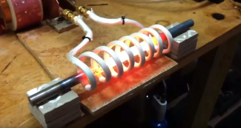
The kit hasn’t launched yet, but you can follow his progress on his GitHub. Induction heating works by magnetically inducing current into the metal, where resistance turns the current into heat without physical contact. The Reactor Forge [Josh] has built runs off of a 220V circuit, and in the following demonstration, heats up a 6″ section of 1/2″ steel bar.
When the bar is cold, the induction heater draws about 1500 W — but once it starts to heat up, it draws more and more, topping out at a whopping 6500 W once heated up.
As far as induction heaters go, this project looks pretty slick. But we love this old induction heater we covered a few years back. It uses a KFC chicken bucket as the concrete mold for the furnace chamber!
[Thanks for the tip Mark!]


Well this is probably more expensive and tricky then a a simple old school charcoal forge but it would have better temperature control.
I’d say it’s probably an inexpensive thing to build but a very expensive way to run up your electricity bill. Induction forges are already available, jewelry makers use them to heat up gold and silver in a small crucible. When I realized the amount of power necessary to reach the liquid melting point of gold, I decided it wasn’t for me.
The operating cost of an induction heater is significantly lower than most other methods (electric, coal, charcoal, even natural gas in many cases). Take for example this part– it took about a minute to heat up and drew 6.5kw maximum. Lets be generous and say that it drew the full 6.5kw for the minute it was running, that is 0.1kWhr, or about 1 cents worth of electricity.
And you don’t need to wait for it to heat up, takes up less space (and oxygen), and clean up is not problem. It won’t replace a furnace or forge, but it has it’s uses, and it’s priceless for small parts.
Except keep in mind that many commercial electrical services charge you a set monthly fee that is actually tiered based on peak draw, so you could inadvertently effectively wind up paying 30 or 40 cents per kWh (or more) and tack on a big monthly fee for that month. Electrical grids don’t like huge power spikes, so they discourage it through higher fees.
The current worst case residential rate in California is $0.36/kWhr, which works out to 3 cents per use worst case. I challenge you to find a cheaper method to heat a bar.
I am not arguing it isn’t cheap. I am just sharing that for many commercial meters, one might be unpleasantly surprised to find that they suddenly went to a different “minimum rate” charge for that month because of a spike in usage, depending on how big the spike is and their specific contractual arrangement. Throw all that out for residential use. Granted, 7,000 watts isn’t actually that much. 70,000 watts would definitely be noticed. That’s all.
This is a silly objection; it’s a 29A device. It’s roughly the same power as an electric cooker or induction hob.
Yes, and if you are a knife maker the flat coil variety will let you heat edges to that it is easier to harden the cutting edge while keeping the bulk of the knife softer. It is called differential hardening.
https://www.youtube.com/watch?v=xEdp4ULeK_4
If one is desperate enough, he can make this simple monstrosity: http://serwis.avt.pl/manuals/AVT2940.pdf
I would like a live mains connected induction coil.There should be an isolation transformer.
I’ve seen worse. One thing that may be a better match would be an output transformer instead (just put a HF transformer in place of the output coil, then attach said output coil to transformer secondary). If you hand wind it and tap it then you can match your coil loading better and get more power out of it.
Death trap and RF jammer in one! I’m thinking if there is a practical way of making it even more dangerous…maybe oil capacitors?
Seriously though, this is probably only a little better then the directly rectified mains plasma cutter (workpiece has to be +) I remember seeing a while back…
The designer actually suggests powering this contraption via autotransformer because of inherent risks and surge currents that without soft-start circuits would trip the fuse. But it has a LED to signal resonance and frequency adjustment, so anyone can tune it up without a scope. One can add a secondary coil and end up with SSTC.
Personally I would stick to metal melter made of MOTs, or maybe an arc furnace, thank you very much.
You would be hard pressed to find an apartment that you can draw 6500 Watts and not blow the breakers.
Indeed
Many apartments have an electric stove. If it is operated with a 240vac service @ 30 amps, that’s 7200 watts. 30 amps is a low ball number, finding 40 or 50 amps would be easily found.
– Jm
If you’ve got a dryer or oven hookup you might be able to. Since most land lords are cheap you’d probably not be able to run that for more than a few seconds before you trip the breaker, 29A of 30 isn’t sustainable.
Not that I’d want my neighbors waving red hot metal around inside their apartments
A 30A breaker has to allow this current for at least several hours, if not defective. 35A on a 16A breaker will trip it in about a minute.
You’re flying close to the sun running this for any length of time on a 30A circuit. This should be run on a 40A circuit to avoid safety, yours and the buildings, issues.
I love the missing wire – the red nut – and the burnt insulation – holy crap!
An electric cooker normally has a separate fuse that is rated for more than that.
Even a single phase 40A dryer breaker would be rated around 9,600 watts.
This is why I don’t rent to crazy stupid people if I can help it.
That’s not a mains junction box with any industry or government approval. That is clearly some half-ass hack.
If I remember right that was a power distribution box in India.
I have quite a few photos of the electrical instaltion work that gets done in India …Truely scarey … One set up even had a few Hindu God figurines watching it to keep an eye!!
I worked at a company that was designing a IOT based power meter for use in India and the stories of the power conditions there are insane. Power just dropping out at any time, same thing with water. Better gated communities/apartment building have backup water and power supplies to keep things going.
Not blowing the breakers is the leas of your worries. Presumably one heats up a chunk of metal in order to make deformable. BY HAMMERING. So I certainly hope all your neighbours are deaf if you attempt this in an apartment…
Holy moly, just looking at this image makes me genuinely feel physically uncomfortable.
What happens as you start to work the metal? Heating up a bar is nice and all but once it’s a hook or some other shape how do you continue?
You use your charcoal forge.
If 1000W is enough. Then simple search on ebay for: ZVS 1000W will give bunch of inductor heaters for ~35$, the only thing missing is included cheap 1000W 48V power supply(some of us have old telecom DC/DC transformers). But it would probably run nicely on 1 or 2 car bateries
Why bother with batteries when you could buy a cheapo welding inverter which is usually around 20 volts?
Nice that Josh is sharing even the preliminary design!
Maybe I have overlooked a link somewhere, but I am missing all the details about the power circuit (IGBT bridge and tank circuit) topology and parts dimensioning.
What would be interesting:
* Does the control circuit avoid reverse-conduction of the IGBTs in order to do without anti-parallel silicon-carbide Schottky diodes?
* In addition to Zero-Current-Switching, does the tank circuit also allow for Zero-Voltage-Switching for a wide range of controllable output power in continuous operation mode?
Also:
* On one of the photos I see a huge electrolytic capacitor directly connected to the IGBT module.
This is odd, because this would require a separate power-factor correction circuit, e.g. a boost-mode PFC.
Operation without at least a passive (50Hz/60Hz choke) PFC is absolutely prohibitive for 15 kW output power – the high-current spikes would otherwise require a line input with 1.84 * 15kW / 240V = 115 A (!) because of the harmonic content of the apparent/AC power for full-wave non-PFC rectification.
I only know the situation for the 50Hz regions of the world where 3x 63A at 230/400 Hz three-phase is the most common household power configuration for new installations. But I doubt that 115 A is common in the USA for non-industrial power circuits.
But maybe this was only a test setup and the final design uses a purely resistive operation mode with a line input filter cutoff frequency above 50/60 Hz but below the RF output frequency range?
correction: 3x 63A 230/400V = 43.5 kW for a power factor of 1.
Tom, thank you for the comments and the intelligent questions. (By the way I just noticed today that this post existed, as I’m siting here working on the latest model.)
IGBT bridge and tank circuit:
I had not included a lot of detailed write up on this yet partly because I settled on fairly standard topologies in regard to the high voltage side of the IGBT’s and the tank. Also because I tried many many different configurations, some slight and some that were out there. The tank in my final setup uses a water cooled matching transformer built on an E core with a ~14:1 ratio and a very low L, parallel connection tank cap and work coil. I’ll work on getting photos on GitHub soon. On the inverter, I no longer use PFC and a filter cap on the rectifier but use the raw filtered DC pulses (120Hz) to feed the IGBT with directly. Although working with clean(er) DC had it’s advantages, clean power control being one of them, the trade off in parts, complexity and lost power to heat and switching losses was not worth it in the long run at very high power levels.
Control circuit, reverse-conduction:
The Hybrid IC IGBT Gate Driver used in the Hybrid Driver module provides the necessary protection for the IBGT’s in a variety of scenarios including reverse-conduction.
ZCS/ZVS:
You can switch between both modes in software.
Huge electrolytic capacitor:
This was when I was testing the PFC, DC boost-mode power control. It used another full size IGBT, driver, a large water cooled inductor and diode. It worked well but I didn’t not feel the power control performance outweighs simple frequency control for the additional parts and complexity. I also use a Three Phase
Half Controlled Bridge (PSDH 175) as a method of power control. It worked smoothly but even with significant snubbing/filtering there was to much noise at high power levels.
I’m sure there are many more questions and I hope to have them all answered before they are ever even asked!
Might be handy for making an annealing ovens which otherwise suck to make.
now that we have a simple way to melt metal… how do you extrude it for 3d printing? :)
MIG.
You run into the same problem as the plasti-drool one – removing heat fast enough so it doesn’t melt…
And fight warping (by the fast cooling). I know of somebody who did research on such a rapid prototyping technology, in the 1990ies, I think at Stanford university. They used an induction coil to heat and melt metal and deposit it for additive manufacturing. IFAIK it was not very successful and we do not see machines with this principle today.
I have the privilege of working with induction heaters at work, and the thought of running one with exposed coil and busswork is a little unnerving. I’ve seen all the youtube videos, and they are all very cool. But I do know that a misplaced screwdriver or wedding ring means at best an induction burn, and contact with coil == death. I hope this project includes proper shielding and work containment in the future. The fried pieces of steel that he shows pictures of at the end is what happens when the work piece overheats and shorts out the coil!
Having repaired some industrial induction heaters, I can say that there isn’t much voltage on the coil (most coil have water running inside and are low ohm) it looks impressive but is mostly harmless. (beware of HF systems)
One point that is not mentioned is that induction heater work on much higher frequency than main, specially if you only want surface hardening or have small/difficult parts.
Yeah, I was doing some more reading, and it seems most of these systems use step down transformers on the output. The ones I’m familiar with run in the KV range on the output side.
Did you mean mV range on the secondary side?
No, they are in the hundreds of volts on the output side of the switching circuit. After they go through the capacitor to form a series resonant circuit, it’s well over 1000V depending upon the load.
On the primary side.
It’s sometimes difficult to understand the circuit, older HF induction heater needed tubes and high voltage to get the higher frequency. So you got a transformer from the main to 5-20KV, HV diodes/triodes HV capacitors, coils and an additional “control” transformer, the output stage transformer (HV to coil) has often ONLY 1 turn which can be very confusing, also the oscillator looks very strange because it’s point to point construction.
I can see that some HV leakage could occur, but the working principe is low voltage, high current.
But again there are probably other application than heat treating, and at huge powers (MW) you can’t get around with low voltage (U*I).
I learned the basics of blacksmithing as a kid on a traditional coal fired forge, personally I would never mess with this home brew induction contraption, it’s not worth the risk.
Besides even if you could use in a apartment, whacking a piece of cherry red hot iron on a anvil with a hammer makes a lot of noise and will attract unwanted attention.
As part of the opening spiel is ‘…especially if you live in an appartment…’ what can one realistically accomplish & build with their hot piece of metal granted they will be shut down so quick if they try to use an anvil / hammer / grind anything?
You can hit the piece with the hammer every time they get a goal at the Superbowl. so no problem…
[youtube https://www.youtube.com/watch?v=dfsCD0WlnjM&w=560&h=315%5D
“Why he chose enchilada night, I will never know.”
There’s absolutely no safe way of doing this in an apartment. I mean, you definitely could do it and I’m sure some crazy bastard out there is doing it, but the risk of burning down the entire building is very high. I personally live in an apartment and I can barely get away with running a dremel. People complain about noise all the time around here. I guess when people are at home they expect to feel like they don’t live in a 12 pack with other people. I’m getting into a house in the near future so I guess the only person I’m going to piss off is my wife.
When I was younger I had horrible neighbors who listened to the worst genre of music possible: disco-polo, which is bizarre combination of folk music with bad disco. They started listening to the same playlist at 7AM every summer morning and stopped around 9PM. So I borrowed a post horn from a friend and used it every morning at 6AM at their door for few weeks…
In my country it’s customary to inform your neighbors, when you are going to make lots of noise, when doing apartment renovation. Using smaller tolls like drills or dremels usually is not an issue. And law forbids making any loud noises between 22PM and 6AM so people can get their sleep…
Thanks for sharing mate.
Regards,
Matt – Birmingham UK
It’s been a while but there is some new content on this slowly trickling out. Here is a high level overview of how the whole system works. https://youtu.be/q-JiucZY7mM