The usual go-to when building a simple robot arm is the ever-pervasive hobby servo. However, these devices are not precise, and are typically jerky and unreliable. They have their advantages, but if strength is not needed a stepper motor would provide much better motion in the same price range.
Those are the lines along which [Bajdi] was thinking when he forked the Mearm project, and adapted it for small stepper motors. First he tried printing out the servo version on thingiverse. It worked, but the parts were not ideal for 3D printing, and he didn’t like the movement.
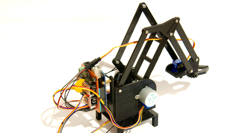
So he purchased some 28BYJ-48 motors. These are tiny little geared steppers that tend to show up in the odd project. He modified and simplified the files in FreeCAD. With the addition of a CNC shield and an Arduino he had every thing he needed for the upgrade. A servo is now only used for the gripper.
The robot is almost certainly weaker in its payload ability, but as you can see in the before and after videos after the break, it is dramatically smoother and more accurate.


Building one of these stepper versions has been on my to do list for a while now. Might reverse engineer back to laser cut parts.
Done, partially, i only converted the base to the stepper and retained the servos. These motors, if you drive them at 5v, rated current and gears have an awesome torque/size, but lack speed compared to servos, it has even a resolution of 2048 steps/revolution, but it is accurate +/-2° due to backslash.
The 28BYJ-48 is the bread and butter of my low powered moving project:)
Awesome! needs more fire extinguisher though.
The trick is to reduce jerk. Jerk is rate of change of accelleration.
First degree curve – constant speed
Second degree curve – constant acceleration
Third degree curve (typical bezier curve) – accelleration changes linearly.
With a third-degree bezier curve, there can be jerk when you move from one curve segment to the next, or at the star and end. If you want to specify the position of two points, and have the velocity and accelleration start and end at zero, you’ll need a fourth or perhaps fifth degree curve.
Making a spline of a series of bezier curves with minimal jerk over the entire path is … an interesting problem.
Yeah – it’s going to have to be fifth degree. You want to acellerate in the first half of the move, and decellerate in the second half. If you don’t want jerk, then the acceleration will be a cubic, so the position will be quintic.
Did you just answer your own comment?
Yes. They haven’t made it illegal yet.
I can’t say that I am quite following you here with the curves thing but I have designed lift controls where the same requirements apply, namely that position is the fundamental function and which is the input to the compensator (error amplifier et al), the first derivative is speed (which has a defined limit in a lift), second derivative is acceleration (also limited so people in the lift don’t fall down or float away) and third derivative is jerk which should be limited so people in a lift don’t throw up or robot arms move smoothly.
I am looking at this as just a compensator design problem that takes only a ‘position command’ input and has a position sensor providing the negative feedback for the compensator.
The limit on first derivative is simply clamping the output of the compensator to limit speed, second derivative is a pole on the compensator output (with due care to stability considerations) or a pole and zero pair in the compensator design (which will be easier to stabilise) and the third derivative is probably best handled by manipulation of the poles and zeros of the compensator to effect an indirect limit on jerk.
I found that with everything else properly controlled jerk automatically fell into line and just wasn’t a problem in a lift project. Given the hugely variable nature of the load on a robotic arm, that may not be true for this project. If the compensator works properly then the arm should slow as it approaches target and the motion should be smooth assuming that the load behaves itself and doesn’t swing freely or any such. So smooth motion should be ok even if jerk is ignored but the jerk under those conditions and assuming fastest possible attainment of target is the design goal then jerk will in effect be maximised rather than controlled.
For minimum time to reach target and zero overshoot the damping factor of the system needs to be 0.86 (Bessel damping) and this could be a bit tricky given the degrees of freedom in this system.
I hope I am not totally off the mark here but my apologies if I am, please ignore my rambling.
So, there will always be jerks when you’r moving from one place to the other and they can be avoided by not suddenly changing direction.
:D
It’s one degree more than avoiding sudden changes of direction. This is why railroad curves have what they call “easing”. A straight section going directly into a radius will produce jerk, even though the direction changes gradually over the length of the curve.
Yes because at the transition the train goes from a straight line to a curve of constant radius, from a constant speed with zero acceleration in any direction (I am making assumptions here) to the same speed but now with an orthogonal, constant and non zero acceleration which will be apparent the instant the train hits the curve which is to say it is an acceleration step from zero to something so the derivative of the acceleration (the jerk) at that point will be (theoretically infinite but practically just) very high.
Sorry for my epic posts. How do you all manage to use so few words!?
In other areas, like 3D printing, “jerk” is considered to be a sudden change in velocity. Like 200 mm/min now, 250 mm/min a moment later. They use it a lot, mostly for changing direction / moving curves without slowing down, simply ignoring away all the non-trivial math at movement junctions.
As long as the arm doses not exceed the tiny pull-out torque of the 28BYJ-48’s light loads (relative to the strength of the arm’s weakest mechanical component) shouldn’t be a problem. I’m not sure at what load the arm will need a feedback system for detecting missed steps…but it probably isn’t very much.
A properly used stepper motor driven mechanism never needs feedback about missed steps. If it does miss steps, it’s simply overloaded and no matter of feedback can compensate for this. On overload, a stepper stops apruptly and doesn’t move again until load is reduced.
Whilst I see what you mean, that’s too simplistic a way of looking at it.
A load that a stepper can perfectly adequately accelerate slowly and maintain speed fine may miss steps if asked to accelerate fast…
e.g move 50 steps over the next 3 seconds may be doable, but move 500 over the next 3 seconds may not.
and feedback can be useful in that scenario if the only objective is to move as fast as possible, but not in a time critical way. (e.g. in the example above moving those 500 steps takes 30 seconds and we don’t care) positional accuracy may be more important than the time taken to get there.