
I was a bit of a lost soul after high school. I dabbled with electrical engineering for a semester but decided that it wasn’t for me – what I wouldn’t give for a do-over on that one. In my search for a way to make money, I stumbled upon radiologic technology – learning how to take X-rays. I figured it was a good way to combine my interests in medicine, electronics, and photography, so after a two-year course of study I got my Associates Degree, passed my boards, and earned the right to put “R.T.(R) (ARRT)” after my name.
That was about as far as that career went. There are certain realities of being in the health care business, and chief among them is that you really have to like dealing with the patients. I found that I liked the technology much more than the people, so I quickly moved on to bigger and better things. But the love of the technology never went away, so I thought I’d take a look at exactly what it takes to produce medical X-rays, and see how it’s changed from my time in the Radiology Department.
The Tube
First things first: what are X-rays? They’re nothing more than electromagnetic waves, living on the spectrum between UV light and gamma radiation, or from about 30 petahertz to 30 exahertz. In principle, X-rays are easy to produce – all you really need is a roll of sticky tape and a vacuum chamber. That’s a trivial example, though, and relies on triboluminescence rather than through the interaction of high-energy electrons with dense metals, which is how medical X-rays are produced. Still, the principle is simple – just produce some electrons from a hot cathode and accelerate them into a target anode using high voltage.
In practice, however, it’s not that easy. While some vacuum tubes can produce X-rays incidental to their main function – the high-voltage rectifiers in old tube-type TV chassis were notorious for this – making an X-ray tube is a tricky business. Even a simple fixed-anode DIY X-ray tube requires a fair amount of skill and some specialized equipment to build, and a reliable, long-lived tube for medical X-rays is a huge engineering step beyond that.

The main problems that medical X-ray tubes – which are essentially particle accelerators – have to deal with all come from the huge energies needed to produce useful amounts of radiation. Thermal considerations are important. First, the cathode has to get hot enough to boil off electrons, which is in the 800° to 1,000°C range. And the voltage between the anode and cathode can easily exceed 100 kV; the kinetic energy of those electrons slamming into the anode can cause it to heat up to 2,500°C at the focal point.
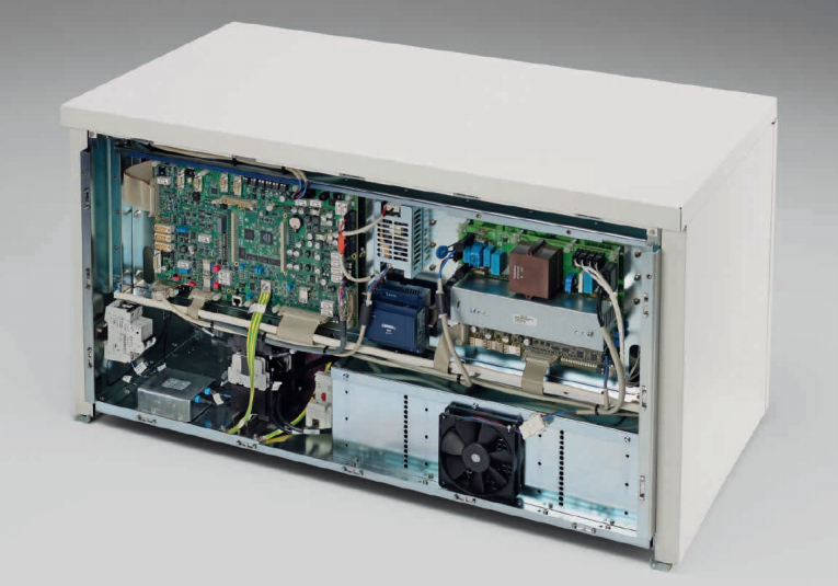
Handling anode heating is a problem that the rotating anode tube was designed to handle. Rather than a fixed target that gets blasted by electrons repeatedly, the rotating anode tube has a disc-shaped tungsten alloy target attached to a rotating shaft. When the technician says, “Deep breath in and hold it,” and you hear a motor start turning, that’s the anode spinning up to around 10,000 RPM. The focal spot of the electron beam is still only a couple of millimeters square, but the fact that a new anode surface is rotating under that beam while it’s on spreads the thermal load out over a greater area.
![Rotating anode X-ray tube. By Daniel W. Rickey [CC BY-SA 3.0], via Wikimedia Commons](https://hackaday.com/wp-content/uploads/2016/05/rotating_anode_x-ray_tube.jpg)

The cathode is a pretty amazing piece of engineering too. More like the electron gun of a CRT than the filament of an audio amplifier tube, the cathode of an X-ray tube shapes and directs the beam toward the target. Tungsten filaments sit in a focusing cup that electrostatically forms the beam. Most tubes have a dual-filament cathode; the technician can select the smaller cathode for a smaller focal spot on the anode and a tighter beam that will image small structures better. Specialized exams like mammography often use tubes with a filament as small as 0.3 mm, as well as an anode made of molybdenum to get a “softer” beam that’s better at visualizing delicate structures.
While electrostatic focusing of the electron beam is pretty simple and proven, newer tubes are turning to magnetic focusing. These designs have a flat filament rather than a cup, and the beam is shaped using magnetic quadrupoles, making these X-ray tubes even more like a particle accelerator.
The Generator
So what powers all this? What kind of electronics live behind those putty-gray cabinets in the radiology suite? In radiology parlance, those cabinets collectively are referred to as the generator, the job of which is to provide all the power and control for the entire X-ray suite. Obviously that means providing the current for the filaments as well as the high-voltage field to accelerate the electrons. But there’s a lot else to run in the tube – the stator windings for the rotating anode, and possibly the signals needed for magnetic focusing. There’s also the power needed to operate the physical support for the tube, the patient table controls, the operator console, and just about everything in the suite.
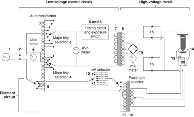
In the old days, the generator was a pretty simple circuit. It basically consisted of an autotransformer feeding a step-up transformer and rectifier for the anode high-voltage, and a low-voltage section to power the cathode. Timing circuitry controlled the length of exposure, and a simple console was provided for the technologist.
Now, generators are extremely sophisticated devices with embedded computers that talk Ethernet and CAN bus. Sleek touch-screen user interfaces are more likely than the old knobs and switches, and special features like automatic exposure control are built right in. But at its heart, the generator’s job is still the same – to heat the cathode and accelerate the electrons.
Even though the engineering has come a long way and the control electronics have changed, an X-ray tube in service today looks pretty much the same as the tubes I learned about 30 years ago when I was in the field. That’s pretty much due to the physics being the physics, and although there are other ways to produce medical X-rays, like Thomson scattering using terawatt lasers or undulators where electrons wiggle through alternating magnetic fields and shed energy in the form of collimated X-rays, the standard X-ray vacuum tube and generator are by far the most practical way we’ll have to deliver medical X-rays for quite some time to come.


Why can’t the motor be in the vacuum tube? Couldn’t you just place a squirrel cage or something inside the tube?
How do you expect a squirrel to rotate the anode if it is inside a glass tube without air, water, or food?
*Slow clap…*
Just give the squirrel a miniaturized self contained breathing apparatus or a scuba re-breather vest. But feeding him and feeces elimination will still have to be engineered into the tube itself.
Half of it is.
Placing the stator winding outside the tube likely has several advantages:
Easier to dissipate heat when not inside the vacuum environment of a tube.
Normal enamel wire insulation can be used, it might off gas or melt under the high temperatures inside the tube
It eliminates at least 2 electrical contacts
If the windings were to fail they can be replaced without replacing an expensive tube
The rotor has to be inside the tube for obvious reasons. It could be something as simple as a permanent magnet (that can can handle the heat, etc…) and suitable bearings.
Either the insulation stability in hard vacuum or the heat dissipation problem are both significant enough to be showstoppers against putting the stator winding in the vacuum envelope. Another is that the anode is sitting at (typically) 40-70 kV, while the stator is at ordinary line potential, but in close proximity to the stator. Vacuum or not, that’s asking a lot of the winding insulation.
And the stator is just a simple induction motor (squirrel cage) armature. No permanent magnet needed.
Magnetic fields and electrons are not a good combination. The magnetic field from the motor would spray the electrons all over the place, making focusing of the beam very difficult. It is much easier to have the motor outside.
I guess magnetically coupling is out of the question due to targeting issues.
Maybe do it backwards and spin the electron beam.
Turn the problem into the solution, magnetise the disc and effectively create a virtual homopolar motor, with the plasma spinning around instead of the disc.
If you need it to stay still, just spin the entire tube at the same rate or use an external wave guide/sheet of millimeter conductors to act as a microwave lens.
Your posting is an example of “how to make something exceptionally complicated”. And yes, the focal point has to be stationary to give a useful image. And your guess is obviously wrong, as “magnetically coupling” through the glaas wall in the form of the rotating field of an induction motor is exactly the way it is done.
Why would you even want it in the tube?
Most small pumps for home heating are built in a similar manner, except the rotor is separated from the stator by a thin sheet of stainless steel.
Brings back memories of my days as a biomed tech. I recall the most wonderful method of checking the timers on the single-phase machines. There was a little brass top-looking thing that you would spin, then take the exposure. Since a 60-cycle machine would produce 120 pulses/second, a 1/10 sec exposure would produce 12 little dots on the film. Totally worthless if you had a newer (that give you an idea of the timeframe!) three-phase machines.
Do… does the top thing have a specific name? It sounds like a rather fun way to measure machine speed, and I admit I love slightly out of the ordinary things like that and reed tachometers and such.
I tried to find the device on Google but vintage radiographs of calibration procedures are near impossible to find.
Side note: I’m never looking for medical x rays ever again. True nightmare fuel.
“There are certain realities of being in the health care business, and chief among them is that you really have to like dealing with the patients.”
I spent 5 years studying to become a medical physicist only to make same discovery as you. Luckily, there were other options open to you when you had a lot of knowledge of physics, radiation protection and an interest in electronics and computers.
Here’s a great thread that may be of interest- http://www.eevblog.com/forum/chat/x-ray-machine-resources/
Does no one else feel bad for the cat?
I can neither feel bad or good about the cat.
+1
I feel both ways… until someone asks me.
Very subtle… LOL
Nice description Dan.
Now, step all that up a notch or two for a current clinical computed tomography scanner: All that stuff has to live on a rotating platform: The tube with rotating anode, its power supply, cooling system, plus the 100 kW 150 kV generator (and a whole bunch of other stuff too).
It all spins at 3-4 revs per second on a modern CT scanner, and that 500kg or so of heavy components is subjected to at least 13 gravities of acceleration. Just balancing one of these things is interesting: it must be dynamically balanced, and the gantry has piezo transducers built in to measure the flex. The gantry flex signal is monitored and an algorithm computes corrections, and feeds back to the tech assembling it to add so much weight at such a Z position or turn bolt X so many “flats” (i.e., one sixth of a turn of a hex head) to move the balance weights or component locations. The initial spinup of every one off the line is done in a cage to catch the flying components. :-)
And you have to get that 100+ kilowatts of 3-phase power onto that rotating platform through some very nice sliprings (thank you Schleifring!), plus control and safety interlocks. Data comes off on another (non-contact) ring at 10-40 Gbits/second in real time.
Fun stuff.
Big ones the rotating part weighs around 1.2 tons with no vibration at that speed is awesome :)
I shouldn’t be surprised. I’m a decade out of the game. I’m guessing you’re referring to the dual-tube Siemens beast — the one that can’t be installed in many existing CT rooms because it’s too heavy and draws too much power…
Where does that 100 kW go? I wonder what percentage goes up in heat in the device versus coming out in X-rays?
Rounded to the nearest percent, the fraction of energy coming out as X rays is zero :-) Essentially all the electrical power going into the tube must be removed by the cooling system (air in the case of a 2-D “plain film” type of system, liquid cooling in CT, C-arm, and other higher performance systems).
Roughly speaking, a CT scan will put 100 kJ of electrical energy into the tube, and produce roughly 100 mJ of X rays getting out the collimator toward the patient. A chest or peripheral plain film might get a bit better utilization, using maybe 1 kJ to produce roughly 10 mJ of x-ray photons.
The rotating anode tubes absorb megajoules of energy over the course of a long study, and radiate the bulk of that away as thermal radiation through the tube wall to the tube housing. A dinner-plate size chunk of tungsten at 2000K can radiate quite a bit of heat…
There are liquid-cooled anodes, particularly in non-destructive testing and other fields. Maybe someone more current than me can comment on their penetration into the diagnostic medical field.
Siemens released a tube with a liquid cooled anode several years ago. Model designation is Stratton. Several different models are now available. MSRP for these tubes run $200,000 to $250,000 (!).
At 2000K the thing is a not so bad incandescent lamp. :-) Seems similar to the argon ion laser tubes: near perfect efficiency as water heater. 45kW in, 20W light out and the rest gives warm water. The jump in efficiency came with semiconductor lasers. Unfortunately solid state X-ray diodes are improbable due to the high quantum energy. :-(
How does the device remove the nearly 100kW of heat without cooking everything WHILE rotating at that speed?
The heater in the house I live in is 30kW peak, and that’s enough for 7 flats over 2 stories :D
At least in part, because kW is a rate, not an amount, and you don’t emit continuously – only in very short sharp bursts
Same as the Gigawatt lasers that fire for femtoseconds
The average power is much lower (at most a few kW). The bulk of the energy during such a high power exposure is absorbed in the anode focal track, and then the entire anode itself, which can safely absorb megajoules. That gets radiated out through the tube wall over the course of a few minutes.
For perspective: a car engine powering a car roaring onto a highway onramp throws off around 200 kW of heat, but the average power while cruising is about a tenth of that. The radiator & exhaust system need only be sized for the average power it must handle.
(30 kW for 7 flats? Must be a kinder climate than mine. My 20 kW barely keeps up heating my 120 sq m on a chilly day (-20C))
30kW heater for a big house? Probably no very cold climate or very good thermal insulation and other means of hot water generation. 24kW is sufficient for a good shower (gas powered instant water heating), but the room-heating gets switched off in this time to get all the power to the water heating.)
He likes fresh air, so he leaves the windows open.
The problem with power ratings of natural gas powered appliances is that they are not directly comparable to electrical appliances. This has two reasons: rated power input has nothing to do with power, but is simply gas flow rate multiplied by some empirically derived constant, which does not match actual burning efficiency of given burner (label on our water heater specifies rated power input of 20.5kW with 17kW of heat actually produced). Other reason is that in general efficiency of electric water heaters, stoves etc. tends to be very high, while gas fired heaters tend to leak significant amounts of heat (in form of heating of exhausts, mostly zero thermal insulation …)
Ok here’s a simple question, if we can take photographs at 10000th of a second why do I have to hold my breath during an x-ray?
Because it’s cheaper to build a system to take a picture in 1/10th second and ask you to hold your breath for a moment, than it is to build a system to take a picture in 1/1000th second…
Also, inflating your lungs gets better contrast in the image between the lung and the stuff they’re looking for.
Also a few other details. The actual exposure time is slow, but you have to accommodate the reaction time to push the button, the motor’s spin up time, and another detail no one has mentioned, the anti-scatter grid, which also has a motor and takes some time. I don’t know about the latest and greatest, but the ones I’ve encountered seem to take a bit under one second to get all the details together. The actual exposure is a tiny fraction of that. The command to take a deep breath and hold still gives a couple of seconds at least for the radiologist to do their thing.
Ok, thanks, that makes sense.
I was wondering why a heat pipe couldn’t be used to move all the calories out of the x-ray cathode.
I suppose because it’s a huge temperature on a tiny spot, but low amount of energy overall. Heat pipes are better for larger areas. Just moving the thing out of the way makes more sense.
Nice article, but two things;
1) You forgot sticky tape as an X-Ray source
2) You didn’t mention the revolution digital sensing has been interns of minimising dosage and using alternate sources (read; nuclear medicine, gamma cameras).
Given I can use a single plate to scan umpteen different patients, with each exposure being sent wirelessly to the cart and then to the computers, with a flat, A3 size panel CCD device doing all of this is absolutely amazing coming from someone just old enough to remember manually back-projecting CT scanstrips.
Plastic scintillators, high-resolution wireless digital plates, low-noise CCDs, all make modern radiography safer, faster and more accurate than ever before.
Also, I loved my Aquillon One at a previous job with 320/640 scanlines and the ability to do a full volume in .2 of a second, winding GB/s over a proprietary blinkenlight bus in the ring (literally, a whole ring of LEDs being read at once while spinning at 200+ RPM. Wide volume size gave me less motion artefact, no patient travel meant less overscan radiation exposure, high sensitivity meant lower doses. These machines are an absolute beauty to behold.
They also break down, a lot!
I was X-rayed a little while ago (and also MRI scanned before that), I was impressed, and curious, about the plastic plate they use instead of film. Was new to me.
I wanted to concentrate on X-ray generation for the first article in this series. If there’s interest in a part two, I’ll make it about the detection end. That’s honestly where all the advances have been made since I was slinging X-rays back in the 80s.
And everyone says vacuum tubes are a dead technology… :)
You should check out MiniMAX! No tubes needed
Thomas F: you clearly misinterpreted what MiniMAX is. It isn’t about the xray source at ALL. It’s a cheap way to make a (rather poor) x-ray detector replacement for film: it is just an alternate method to read out a standard phosphor plate detector that uses a digital camera instead of a flying-spot readout. It make no claim whatsoever about the x-ray source — it just uses whatever is normally used. The original paper used a rather ordinary pulsed industrial source: 30 year-old technology (invented in Ann Arbor, MI!).
LOL schrodinger’s cat I see what you did there.
hello, what is the exhaust tip in vacuum tube?