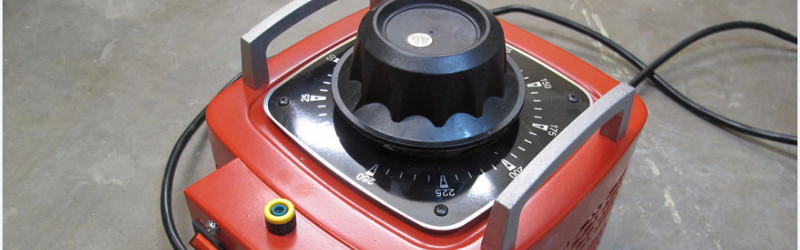
The folks at TOG, Dublin Hackerspace, have a large variac. A variac is a useful device for testing some fault conditions with AC mains powered equipment, it allows an operator to dial in any AC output voltage between zero, and in the case of TOG’s variac, 250V.
Their problem was with such a magnificent device capable of handling nearly 3KW, it presented an inductive load with a huge inrush current at power-on that would always take out the circuit breakers. Breakers come with different surge current handling capabilities, evidently their building is fitted with the domestic rather than the industrial variants.
Their solution was a simple one, they fitted an NTC surge limiter in series with the variac input. This is a thermistor whose resistance falls with temperature. Thus on start-up it presented an extra 12 ohm load which was enough to keep the breaker happy, but soon dropped to a resistance which left the variac with enough juice.
This is a simple fix to a problem that has faced more than one hackerspace whose imperfect lodgings are wired to domestic-grade spec. In a way it ties in neatly with our recent feature on mains safety; making the transformer no longer a pain to use means that it is more likely to be used when it is needed.
Via: TOG, Dublin Hackerspace.


Just get soft start circuit from any MOT-design (not SMPS) microwave. It tamed the beast, 10A Krizik variac 0-250V.
Try this one i’ve designed:
http://wiki.spoje.net/doku.php/navody/electro/active_softstart
http://i.imgur.com/W2slF0e.png
That’s pretty clever! Ideally, you would switch on the triac on the half-wave opposite to the last half-wave supplied to the transformer when it was switched off, which would prevent the residual magnetic field from adding to the core magnetizing field and further reducing core saturation, but I don’t see an easy way to do this.
You could use zener diodes instead of the TVS, if you connect 2 identical ones in anti-series. Personally I would reduce the TVS/zener voltage by about 30V and place a DIAC in series, this would ensure a “snappy” trigger current for the triac (the voltage across a DIAC drops sharply when it’s triggered). One of the possible failure modes of triacs and thyristors is insufficient gate trigger current and low rate of rise, leading to hotspots and device failure. Since you’re only triggering the device once instead of every half-cycle, it will probably be okay.
I’d be wary about high current loads with that thermistor. The datasheet mentions 15A maximum steady current but that is at 25C only.
A better option is what RBMK said above. Have a chunky power resistor inline which gets bypassed by a mains rated relay after a few seconds. You won’t have issues with a 200C+ thermistor trying to pass 13A this way.
I used to use three light bulb sockets connected in parallel together and then in series with the load. You can choose the power balance by choosing what power light bulbs you put in the sockets but I was using that for lower power levels.
A line voltage coil relay and a large resistor are all that are needed. The coil is in parallel with the variac and the resistor is in series with both and the no contact is across the resistor. By the time the relay contact engages a few cycles have occurred bringing the variac up enough in impedance to not trip the breaker.
I’ve got the same problem with a 3KVA variac. Trips all my breakers (type B and C). I was thinking of making a zero-crossing SSR/triac but I just read in the link about using peak voltage instead… Glad to have read that, will look into it.
It’s not often I need the 3KVA variac, most of my testing gets done with a smaller 150VA one, works nicely for short tries at about 500VA
We used to use Variacs all over the teaching labs. Not allowed anymore. Remember they are not an isolation transformer and the “neutral” wire is passed straight through without a switch on mos if not all. The switch just interrupts the “hot” side input. If is is plugged in wrong, has a non-polarized plug, or there is a possibility of live voltage somewhere in your circuit, a Variac can give you a bad case of death. On the other hand, mighty handy for variable AC at reasonably high power.
So put an isolation xformer in ahead of the variac. Easy fix. Heck, live it up and go isolation xformer>GFCI>variac. Throw a kill-a-watt on after the variac to track your voltage, current, and frequency. Great test bench solution.
I just did that, but i put the isolation transformer after the variac.
I find it hard to believe. Since inductors OPPOSE current change (i.e., v = L di/dt), and are normally used to reduce spikes in current (main problem is they can spark when turned off, again they are used sometimes for this too). So I do not see how it is possible that an inductive load will have a “huge inrush current at power-on”.
trolling? got to be trolling. on initial power up the inductor appears to the incoming supply as a short circuit. an inductor can indeed oppose current change if it is in series with a load.
You do not really know what you are talking about. Capacitors act as short circuits upon connection (i = C dV/dt). Inductors are the opposite. Please review your EE courses again.
yeah dito.
If you were talking about a series inductor then you are completely correct.
A series inductor has this effect because it causes a changing voltage to be converted to a magnetic field and this magnetic field then causes (induces) a voltage when the original incoming voltage collapses. This is completely different to a secondary where the magnetic field is being generated by the primary (sine wave) so the internal impedance of the power supply is not characterized as a series inductance.
Then the load itself – well you said it yourself “Since inductors OPPOSE current change (i.e., v = L di/dt)” so it opposes the initial application of power ie – like a short circuit in DC.
No. This does not work this way. You need to review your calculus and EE courses.
It’s caused by core saturation; starting at 0 flux at the zero crossing of the voltage (worst case turn on point), instead of maximum flux in the opposite direction, means you get twice the normal flux in the core by the end of the half cycle (remember, the flux is at a maximum when the voltage crosses zero). This is far more then the iron core can sustain, which heavily saturates, which in turn dramatically reduces the inductance and the current is only limited by the wire resistance and the little inductance that remains.
Hi Guys,
the NTC, if properly mounted (e.g. using a porcelain connectors/terminal block), is not only the easiest solution, but also more safe than using a relay to bypass a conventional resistor:
A relay has a limited live-cycle – and what is less well-known: a high-power relay (using silver or similar contact material) needs a certain minimum switching power in order to break the oxide layer on top of the metal contacts. This is by design.
So what happens: The relay /will/ fail sometime in the future. Then the series-resistor overheats and if you did not place an overtemperature safety fuse in proximity to the inrush-limiting resistor, you are left with a nice cigarette lighter appliance…
Of course, an NTC can fail, too. So anyways you need a proper housing and mounting. E.g. heat resistant connectors/terminal blocks or soldered into a suitable board/connector with long-enough leads and big copper traces to allow the NTC body to be at approx. 200..230°C at full-load while leaving the PCB below the permissible temperature.