There are plenty of electronic components out there, but the one we tend to forget is the most basic: wire. Sure, PC boards have largely replaced wire with copper traces, but most projects still need some kind of wire somewhere. Once you need any wire, there’s a good bet you will need longer wire, and that means splicing one wire to another. Simple, right? Not really. There are a variety of ways to splice wires, and which one you use depends on what you want to do and the type of wire you are using.
If the wires touch, good enough, right? Not necessarily. You need enough contact area for the current you are drawing through the wire to flow. It is also nice if the splice can survive some amount of mechanical strain, vibration, and survive getting hot and cold repeatedly.
Usually, after splicing, you’d like to solder the connection, although depending on the application, you don’t always see that. At the very least, you’d want to wrap it in electrical tape, use heat-shrink tubing, or otherwise insulate the bare wires and maybe provide a little mechanical support or strain relief.
Keep in mind that there are connector options, either mechanical, crimped, or soldered, that allow you to avoid splices. Soldering to a terminal strip, for example, or scewing wires into a barrier strip will get the job done. So will a butt connector, a wire nut, or a WAGO connector. But sometimes, for whatever reason, you just need to attach two wires to each other. It’s been done before.
The Gold Standard
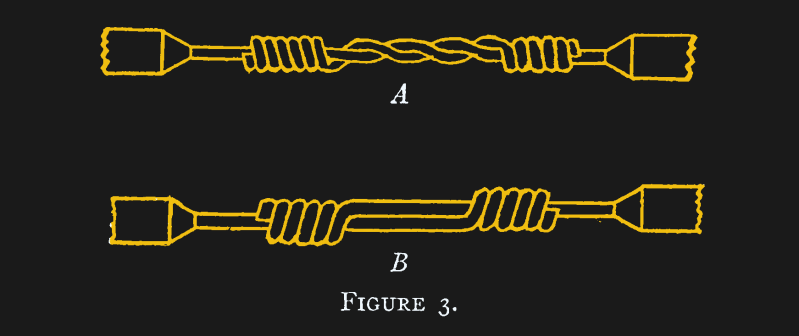
Arguably, the best way to join two similar-sized solid wires is the Western Union splice, or the lineman’s splice, which goes back to at least 1915 when the book Practical Electric Wiring (PDF) described it. It will work with stranded wire, too, if you twist it tightly and, even better, tin the wires first.
You essentially bend each wire around the other and then tightly wrap each wire around the other wire. There are a few options about how to handle the middle part, as you can see in the adjacent figure.
These aren’t hard to make, but it does depend a bit on the skill and patience of the person making the splice. On the other hand, they are mechanically very robust.
NASA’s workmanship document (NASA-STD-8739.3, PDF) urges you to avoid splices and prefer controlled processes like crimps, where a tool produces repeatable connections. However, in testing, soldered Western Union splices were found to be quite strong, usually stronger than the wire around them.
Other Common Splices
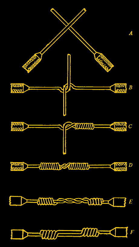
Perhaps the most common splice is the rat or pig tail splice. That’s where you just twist two wires together. If you don’t have to survive mechanical tension and you have solid wire, this works ok and is what you often see inside electrical boxes in North America, either made by or topped with a wire nut.
These are fast and simple, but without something like a wire nut, a bit suspect. They tend to loosen over time, especially under vibration.
Another problem is when you have very large solid wires that are not practical to twist. That calls for a Britannia splice. Here, you put two presumably thick wires end-to-end and bind them with a smaller wire. You don’t see these very often, although you may see them in some utility contexts. More often, you’d crimp a butt connector to join two large wires. Note the binding wire wraps around both wires and the common part where the wires touch.
A similar splice is the so-called fixture splice, in which a smaller wire wraps around a larger one. This is another case where you would almost always finish this off with some kind of mechanical connector, like a wire nut.
Sometimes you need a splice that isn’t much larger than the original wire. You can do that with a scarfed splice. This is usually only practical for large, solid wires. You essentially taper each wire to a point (using, for example, a file) and then bond them together much like a scarf joint in carpentry. Of course, you must solder or somehow fix the wires together, as there is no mechanical connection. This takes a lot of work and also takes skill to get right.
Specialty Splices
Sometimes, you want a splice into an existing wire to form like a “T” or a tap. It is possible to create a tap joint by removing insulation from the main conductor and then wrapping wire around the bare metal. Often, you’ll tie a knot in the tap wire before wrapping to try to improve the mechanical hold a bit.
However, these are not especially strong, and you have to be careful removing the insulation so as not to nick the main conductor and weaken it or reduce its current capacity.
If the main wire is stranded, another variation is to carefully split the main conductor into two segments and then pass the tap wire through the center before wrapping it as before. While this might be slightly more mechanically advantageous, it is still not a good replacement for a crimp-on tap or a connector to hold three wires.
Splicing multiconductor wire can also pose a challenge. Sure, for a lamp cord, it is just as simple as making two splices. But in cables where the pair is balanced, it is often impractical to maintain the spacing and twisting of the wire. Better to get a cable of the proper length.
Probably Others
There are probably as many ways to make a splice as there are people making splices. Some are clever, others are terrible, and a few — like the Western Union splice — have stood the test of time.
Most of the time, you want to avoid splices where you can. Try a terminal block, a solder sleeve, or a crimp connector. Even a wire nut, while technically a splice, will give you some mechanical advantage over just twisting wire together.
We favor the Western Union splice with a good coat of solder. In the end, the “right” splice is the one that matches the electrical load, mechanical demands, and environment you expect it to live in. A quick twist might work today, but a properly executed splice will still be working years down the line.
What’s your go-to method? Let us know in the comments.


In spite of NASA not liking splices, the Western Union splice is also known as the NASA Splice
“And, even better, tin the wires first”, Al? Do up a ‘western union’ with tinned wires? If it’s tinned wire (copper), sure, but with solder-tinned wires — no way.
Wasn’t the western union supposed to hold up without solder? IMO – unless you’re doing a cable run – don’t worry so much: make a couple of J’s (make a good job of that), solder and shrink (or tape, or tape and shrink).
Yeah, I thought the two mentions of soldering was odd. The only reason I ever do a Western Union splice is when I want the cable to remain strong and not be embrittled by adding solder.
I think it comes from here:
“19.7.1 The following requirements apply for Western Union/Lineman splices:
a. The conductors shall be pre-tinned.”
https://nepp.nasa.gov/files/27631/NSTD87394A.pdf
page 71
I would expect them to crack the tin when splicing but maybe I put too much tin on pre-tin.
TIL that the splice I’ve always used when soldering is suboptimal. After crossing the wires, I always wrapped each wire around its own base (rather than the opposing base). Looking at the western union splice makes me see that my splice concentrates strain in one spot when the wires are pulled, and gives a relatively small area of contact between the two wires.
Of course I’m dealing with 3.3v wires on an ESP32 so technique probably doesn’t matter much :)
My takeaway from the NASA document was that clear heatshrink is a thing. So you can see that whatever is going on within is correct.
I now use it all the time, unless it has to be pretty to non-techies!
Clear heat shrink is amazing. But I never use it for your purpose.
Get a 20 euro/dollar label maker from the jungle site, print out a label, put it on a wire, put a clear heat shrink over it, make it look like a million bucks. The heat shrink makes the label stay there.
Even better: Print out a color label with a conventional printer on self-adhesive label paper, and secure that on the cable with clear heatshrink. It stands out.
Sounds problematic. I don’t have a conventional printer and I don’t know how others work but I don’t know everything in advance. Label printer is so much easier and also looks neat.
A label sheet can only go through the printer a couple of times before the labels start peeling off inside the printer and make a huge mess. If you’re just making a few labels, then most of the sheet will go to waste.
The label maker is a lot more convenient if you need a smaller number of labels. The label tape is available in lots of different colors.
Not been our experience – most of the time the whole sheet is used in one or two goes, but plenty of times it has done way more through our laser. So I’d suggest it depends almost entirely on the printers print path, with most printers that have a manual paper feed probably being print as many times as you like if you use it (as the manual feed tends to be a much straighter path to deal with, and I’d bet it was the curve around the rollers that caused your issue.).
Clear heatshrink, or at least some of it, is not UV stable and deteriorates quickly where the black does not.
Also the glues used inside glued heatshrinks are various kinds. Some are PVA – which is water soluble, others deteriorate after a couple of years into goo, without liquid water.
Watching the Brittanica splice, I kept thinking
“Wow, so that’s how you wind a lure for electricians!”
Britannia*
Not the dictionary.
Rule, Britannia !
Not the goddess.
Rule Britannia!
Marmalade and Jam
Five Chinese crackers up your arsehole
Bang bang bang bang bang.
Just thought I ought to share the lyrics for those who might not be familiar with the tune….
What I learned for this splice is done a bit differently then the video
The hook is a moderately sharp 90 deg, start at the center of the lap with the center of the splice binding wire and work to both hooks, about ten wraps or so. Tighten, bend the hooks over the rest of the way to the outside of the binding, then five tight wraps on the base conductors outside the hook.
No solder needed, doesn’t move, Good strain relief, corrosion resistant if bound TIGHTLY, even bare.
When I was still using this style, many years ago, I tried to shrink wrap the splice, even on uninsulated wires, to reduce slippage. On insulated wires, The insulation was trimmed to just clear the base conductor wraps, and ALWAYS shrink wrapped, marine type shrink (goo-filled) if possible.
Don’t forget that soldering stranded wire creates a stress point where the wire leaves the solder – technically a thing with solid core wire too, I guess. Hence the crimp I believe.
And yeah I’ve seen Hackaday posts about this before, but this is good and bears repeating now and again.
Yes, that’s a good point to remember. Soldering stranded wire is electrically good, but mechanically suboptimal, especially if the wire will be subject to flexing. If you can mechanically support the wire such that the end of the solder joint isn’t subject to any mechanical stress, it shouldn’t be a big problem. But I’ve seen lots of professionally made wiring harnesses for airplanes and cars, and they all use crimp connectors for stranded wires. Then again crimp connectors are only good if they’re made with the right tools, crimping the right connectors onto the right kind of wire with the right amount of force.
“crimping the right connectors onto the right kind of wire with the right amount of force.”
That’s why most of the crimping tools have a ratcheting system that releases when crimped properly. If you can’t get that crimped then you did something wrong and the crimping isn’t reliable.
my usual solder splice is i just lay the two wires parallel to eachother, coming from different directions (so it isn’t a pig tail), thoroughly tin them and then melt the solder together. If i’m lucky, the heat shrink tube i captured even fits around the splice! Luckily, i haven’t had to splice for mechanical strength.
I’m sure it’s braindead but it’s better than what i used to do :)
50 years of wire splicing and I’ve never had a joint like this fail unless the wire is being pulled or otherwise stressed. Wrapping a wire around another wire creates stress.
I’m not sure what could possibly be worse than this
same technique but with a pigtail of twisted-together wires :)
And a huge lump of solder ‘drip’ built up all over corroded wire nest.
‘Jackson Pollack’ soldering.
The solder didn’t wick up the wires.
Buy a crimper dude. They’re not expensive.
Ahh, but the ones that do an acceptable job are expensive, though. Especially when you factor in the required annual certification.
The trouble with a crimper is you have to know the size of your wire. i use the same idiot approach for whatever wire i happen to come across, mostly between like 14awg-28awg, solid and stranded. honestly my hope is you’ll tell me “look at this crimper, fits all those sizes” but from my perspective of ignorance, that’s a steep learning curve :)
the only crimper in my life is for ethernet ends, which is always the same wire
Those expensive crimpers have dies, charts, specs and presets for every wire gauge, terminal housing combination, etc. Harnesses are no joke, and the termination is even more critical, especially in aerospace.
Except, good ones actually are.
1 crimper?
LOL
Cat5/6, JIS, Automotive wiring, structural cables…
Don’t but the cheapest crimpers.
But the annually certified $1000 one is like an annually calibrated meter/scope.
Needed where the thing is life critical or otherwise required by law and actual enforcement.
Otherwise waste of time and money.
Entrenched interests maintain the same calibration schedules as when the things had tubes.
Also some crimpers are easily bodged.
e.g. Ribbon cable clamp on connectors work fine with a bench vice and a close eye on alignment.
I believe that solder was used in 110v connections in the 1950s but over time caused fires. Surges cause the solder to melt and eventually oxidize, the oxides caused resistance and resistance caused heat.
If the Wire gets hot at the Solder Splice, you did not get it tinned well. Agreed it’s hard to do a proper splice job in a confined space of an electrical wall box.
A properly applied splice will have NO heat buildup as viewed with a thermal camera.
I find simply laying the ends of the wire in parallel for 1cm and soldering makes a joint stronger than the wire, at least for typical hookup wire for electronics projects. Even on zip wire (like on AC power cables) a 1cm overlap joint is stronger than the wire.
“We favor the Western Union splice with a good coat of solder”
Uh, doesn’t that undo a significant portion of the mechanical strength that the method provides?
nah it just puts a big inflexible slug in the middle of the wire. the slug is usually solid but the ends at the edge of the solder tend to not flex well and can break, especially with stranded wire. some strain relief is recommended. heat shrink is usually enough though i tend to apply 2 layers. if its a fat wire i like to bind the insulation at both ends with a bit of stiff bailing wire, wrapping the completed splice, so the bailing wire takes the load and tape and/or shrink over that.
i usually do a soldered wu. if im in the field i also usually keep some flux and solder in my box. il apply flux to the splice, wrap it with solder and break out my lighter. not as clean as a bench join but it usually works.
When I was a child doing electric fencing for my grandfather, the usual was a modified Western Union splice. Like the picture here, but leave a couple of inches on each end, then bend the ends back towards the middle and twist them together.
Yes, Wago 221.
if you aren’t humming the theme song from the a-team while doing your splices, you are doing it wrong.
Likewise, plugging two extension cords together requires the Back to the Future theme.
Don’t be cheap, use a Wago. Don’t burn your house down.
Wagos are not code-compliant outside of EU. When they develop a fault they tend to melt and expose bare conductors causing a risk of electric shock, fire or explosion hazard.
Just so everyone knows, none of these are code compliant in North America anymore.
I should elaborate, not code compliant for line voltage, which is technically low voltage. Extra low voltage is the 24vac/dc etc voltage people tend to think of as low voltage. At least defined by code here.
Such a vibrant and active comment thread on splicing. I think we’re officially nerds. Fr tho solid read article and thread