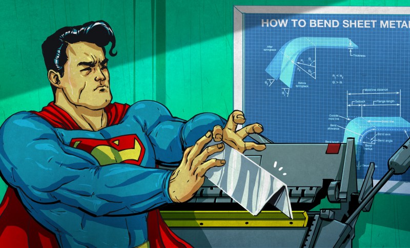
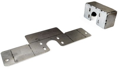
A motor mount. A sturdy enclosure. A 43.7° bracket. The average hack requires at least one angled metal part, and the best tool to make one is still the good ol’ press brake. Bending parts requires a few extra thoughts in the design and layout of the flat patterns, so if you want to know about bend allowances, bend deduction and how to bend accurate parts even without a press, read on.
Bending methods
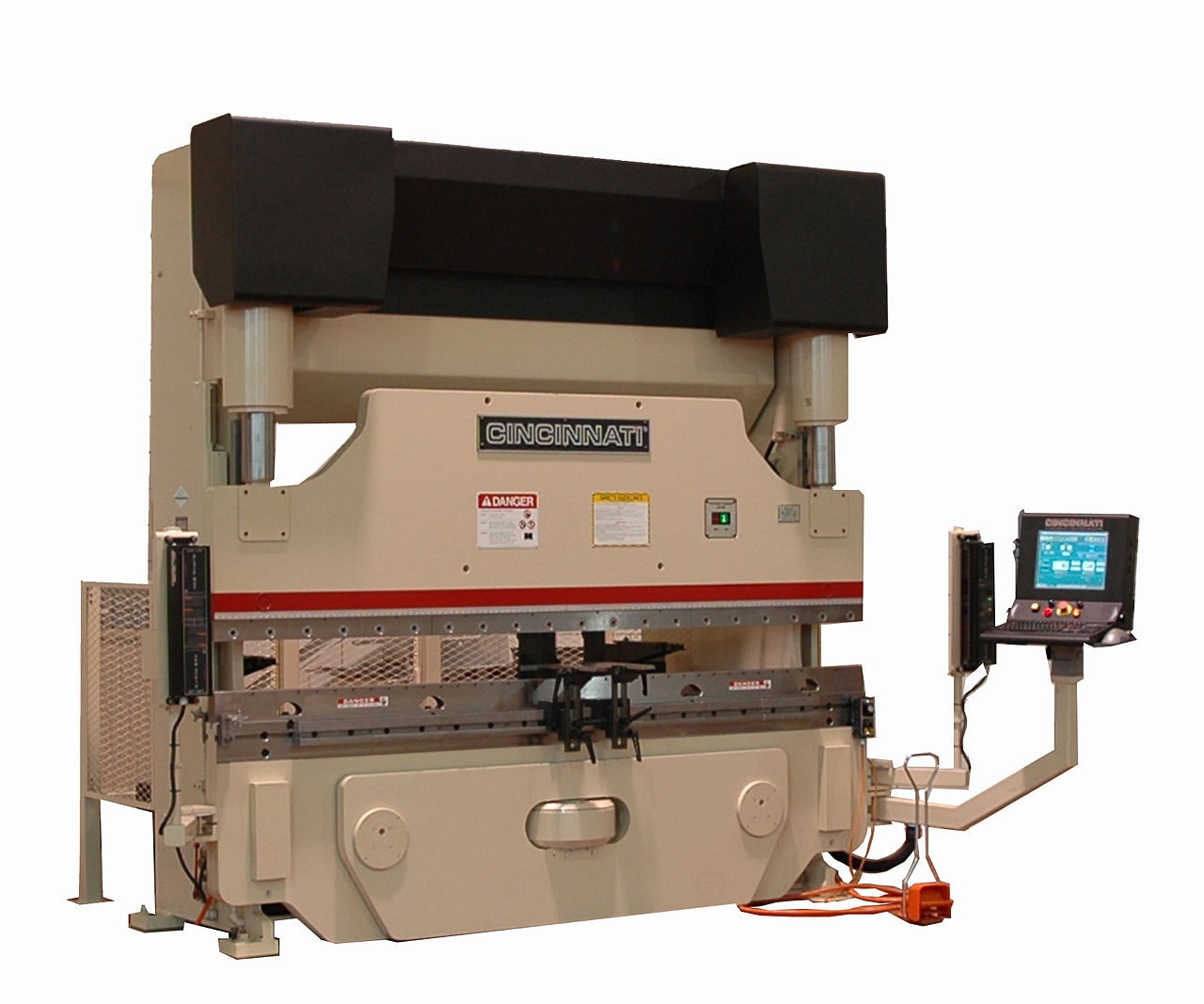
The most common bending methods, but surely not the only ones, are air bending and bottoming. They can be done on the same press brake and usually don’t require more than 25 tons of pressure for general purpose workshop use. A press brake also comes with a manual or CNC-controlled back gauge that allows positioning the bend line accurately. Just like all presses, press brakes are a bit deceptive about their danger potential. They look calm and move slowly, but the moment their force hits the material, things can happen very fast.
However, if you can’t get access to a press brake, you’re not completely out of luck. There are slotting techniques, where the material is weakened at the bending line just enough to place a nice bend into up to 1/4“ steel using nothing more than a bench vise.
Air bending
Air Bending uses a punch tool and an often V-shaped bottom die. The profile of the punch defines the bend radius while the stroke depth defines the bend angle. Since the stroke depth is adjustable on the machine, air bending lets you bend sheet material to an arbitrary angle without replacing the die or punch tools. The opening of the bottom die should be chosen adequately depending on the material thickness and bend radius, and a good rule of thumb is 6 to 12 times the material thickness. Doing so will ensure good results and a long tool life. However, you’ll quickly notice that even professional workshops use their 3/4“ bottom die for just about anything, so that’s that. After the punch is released, the material will spring back a little, which must be compensated by overbending the material. Air bending is not great in terms of angular accuracy but can accommodate different materials, material thicknesses and bend angles without retooling.
Bottoming
Just like air bending, bottoming uses a punch and a V-shaped bottom die. However, the punch will press the material against the inner surfaces of the bottom die, so the angle of the bottom tool defines the bend angle. Therefore, the method requires separate bottom dies and retooling for every bending angle as well as significantly more pressure. However, it is more accurate and has less springback than air bending. What you will usually find in a general purpose workshop or makerspace is a brake press equipped with a 90° bottom die for bottoming, and for any bend angle smaller than 90° the same die will be used for air bending. However, since bottoming involves greater forces, it is also more important to use the right dies. A rule of thumb says that 8 times the material thickness makes a good bottom die opening. However, since the geometrically correct opening also depends on the bend radius, there are better ways to calculate the opening width.
Slotting
To define the bend region and reduce the force required to bend a part out of sheet metal down to something you can handle without a brake press, slots can be cut at the bending line to selectively weaken the material. It is similar to kerf bending, but less flimsy. Slotting is a great technique to get custom metal enclosures and frames for small robotic projects and even large unloaded structures. However, since it obviously weakens the material, it’s a no-no for heavy load-bearing parts that rely on the structural integrity of the bend region. There are even patented methods using certain slotting patterns, and even if the idea behind them is simple enough, they can be quite ingenious.
Bending geometry
Depending on the bending angle and radius, the material in the bend region deforms. To get the final part dimensions we aim for, we have to take this into account beforehand. Most professional CAD tools, such as Solidworks or Rhino, will do all the bending math for you, but unfortunately, many other good tools, such as Fusion 360, OpenSCAD or FreeCAD require you to get additional plugins, make use of online calculators , or do the math by hand.
Sheets
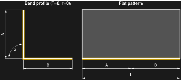
Let’s start by assuming you wanted to build a 90° bracket out of an infinitesimally thin sheet of material, or to be practical, a piece of paper. Because it’s so thin, it actually does not contain any material, so it will bend without material deformations. To make it even simpler, we choose a bend radius of 0, which makes it a crease. In this theoretical case, the length L of the strip we need to cut out will be the sum of the two sides of the bracket, A and B.
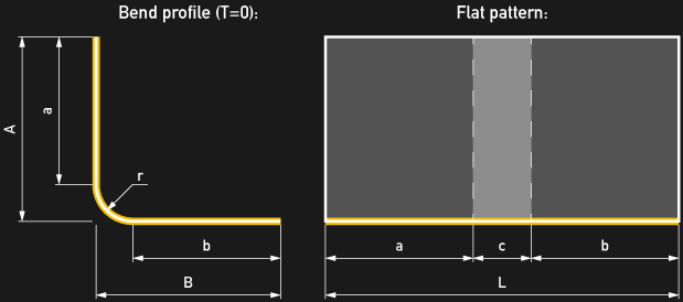
If we now add a bend radius, our bracket will not consist of two straight sides A and B anymore, but by two shortened legs, which I will call a and b. The legs are connected by an arc of length c. So far, so good.
Cuboids
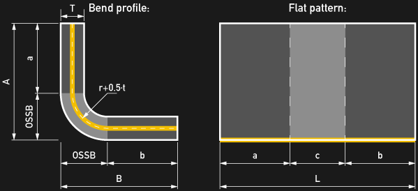
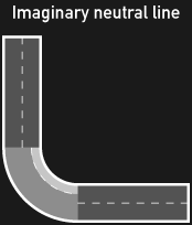
To think about bending a sheet of metal that has appreciable thickness, focus on an imaginary central sheet, the so-called neutral line or neutral axis, within the thickness. This neutral line behaves just like the thin sheet above, remaining undeformed during bending. The only two things we have to bear in mind mind are that the material thickness t offsets the bend radius r’ of the neutral line by half the material thickness, and our legs a and b get a bit shorter. Real-world materials like steel and aluminum do not behave exactly like this central line, but the concept of the neutral line is still useful to describe them.
Bend allowance and k-factor
As always, real-world materials do not behave as simply as our models. After the material has taken on its new shape in between the hardened steel tools of the press, this central neutral line will be pretty messed up by the interaction. We can’t really know the course of the neutral line after the bend without a detailed and rather complex model of the material characteristics. To make things easy, an imaginary neutral line based on a simplified approximation can be used to predict the length of the flat pattern:
To do this, a correction factor, k, is introduced. The factor offsets the neutral line piece in the bend region from its center path until it has the length of the corresponding region of the flat pattern. The k-factor is empirically determined for a given material, material thickness, bend radius, and bending method. It reflects all real but unknown distortions in the bend region.
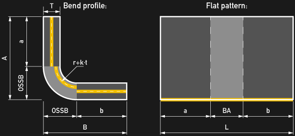
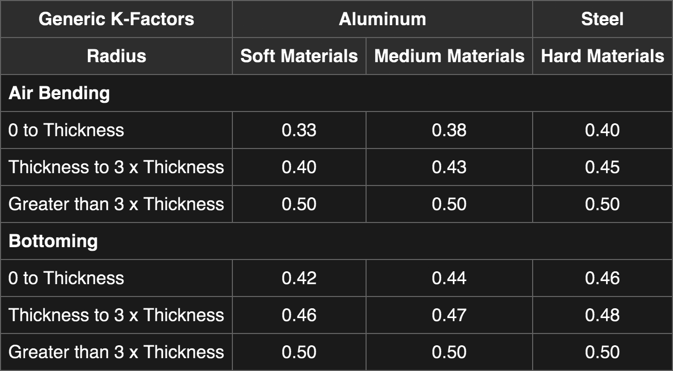
Since the k-factor depends on several factors, tables of empirically determined k-factors for given setups are used. Using the k-factor, we can now calculate the bend allowance „BA“, which is the length of flat material that goes into the bend region. It’s simply the arc length of the „imaginary“ neutral line piece, that has been offset by the k-factor:
![]()
Of course, the approximation is only as realistic as the k-factor used, and it makes sense to keep your own table with k-values for the materials you intend to work with. However, the following values are a good starting point:
Bend allowance of slotted bends
When slotting sheet metal at the bend axis, the material’s average density in the bend region is decreased. There is no particular rule for how much the material should be weakened but as a rule of thumb, a density of 20% for up to 1/8″ steel is a good choice. Going with 20% density, the bridge width w is 1/4th of the slot length s as shown in the graphic below. For the bridge width w, I suggest not going below 3/4th of the material thickness T.
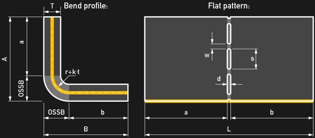
Straight slots
When using straight slots, the bend region in the flat pattern will be as wide as the slot width d, so for all practical purposes, the slot width is equal to the bend allowance in this case. Depending on the desired bend radius, the slot width can be calculated:
![]()
However, the radius should not be too large, and as a rule of thumb, it should be below 2/3rd of the material thickness.
Engineering slots
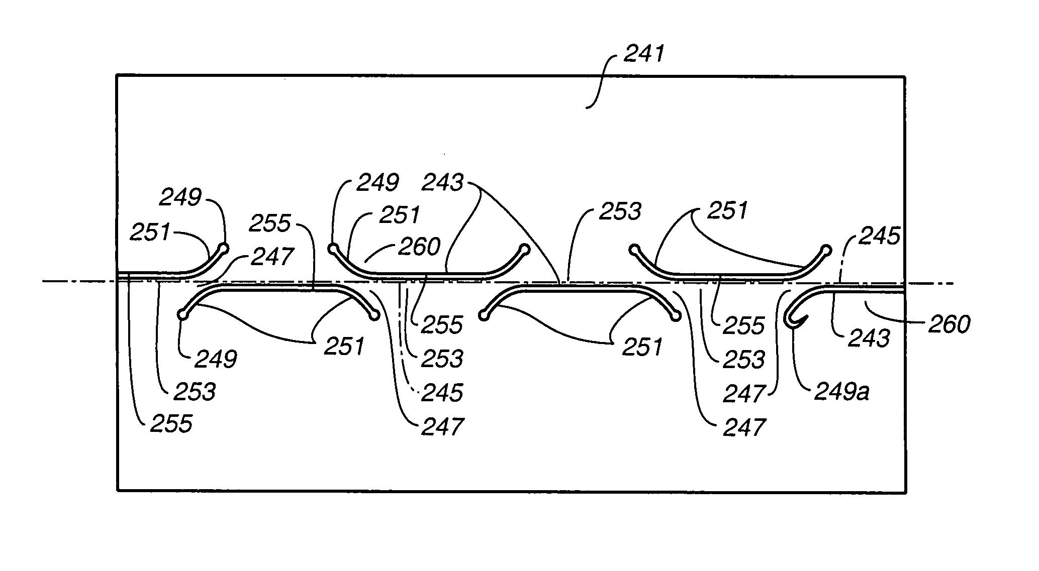
Slots can be shaped in a way to control the bend in a more predictable and material-independent way. While cutting non-straight slots into metal may sound trivial, there are still lots of patents in this field. For educational use and DIY-projects, the related patents by Industrial Origami Inc. may still be a great resource. They contain a whole catalog of more intelligently engineered slot patterns, such as the smiley-shape, the self-indexing hinge, a twisted hinge, and other origami-like methods.
Most of the patterns are designed in a way that allows the material to self-index against itself after the bend has been made. For example, the diagonal bridges of the smiley pattern will shorten as they are twisted by the bending, effectively pulling the two flat sides together edge-to-edge, so there is practically no bend radius and no material dependent bend allowance to account for. This method allows for very accurate bends with neglectable deformations and remarkably strong parts. The formula for the outside setback can still be used, and since the OSSB is purely geometrical, no k-factor tables are required.
Outside setback “OSSB”
To get our flat pattern length L, we have to know the length of our the straight legs, a and b. Of course, if you design a part using CAD, you can just read the dimensions from your CAD tool. However, in case you just have a technical drawing with only the essential dimensions – or a sketch on a napkin – you’ll have to do that manually.
The difference between a side length (A or B) of a bend and its leg (a or b) is called the outside setback or “OSSB”. So the leg’s lengths are defined as:
a = A – OSSB
b = B – OSSB
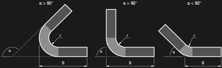
At this point, there are two different definitions of the side lengths A and B is commonly used, and it depends on the bend angle. For bend angles smaller than 90°, they are usually defined as the length from the apex to the edge, for bend angles larger than 90° they are usually measured from the tangent of the bend to the edge. For a bend angle of 90°, those two are the same. In all formulas and examples, degrees are used for the bend angle α.
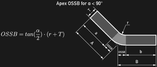
OSSB for α < 90°
For a bend angle α smaller than 90°, and generally, when A and B are dimensioned from the apex to the edge, the formula for the outside setback is always dependent on the bend angle:
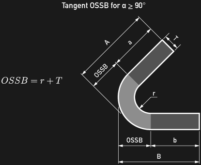
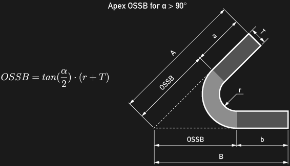
OSSB for α >= 90°
For bend angles larger than 90°, and generally, when A and B are dimensioned from the tangent of the bend to the edge, the outside setback is independent from the bend angle:
Freedom of choice
Unless you’re bound to a certain norm, you can still dimension A and B from the apex to the edge and use the first formula, even if your bend angle larger than 90°, as long as it is smaller than 180°. Still, for larger angles, this becomes highly impractical, given that the apex moves far away from the bend.
Flat pattern length
 Finally, we can put everything together and calculate the flat pattern length L that we need to cut the metal to by putting the pieces together:
![]()
Bend deduction “BD”
In practice, the flat pattern length is always shorter than the sum of A and B, so everything above can be condensed in the difference between A + B and L, which is called the bend deduction „BD“.
![]()
![]()
For α <= 90°
![]()
and for α >= 90°
![]()
Design your part now
So, knowing the basics about bend allowances and bend deductions, you should be able to build your own custom steel enclosure, robot frame or mounting bracket using a brake press or the slotting method and a vise. And you don’t need to own a laser or plasma cutter to get custom shapes out of stainless steel or aluminum. Local workshops and online services will happily feed your design into their highly automated fabrication pipeline and even small quantities can become affordable. To round this up, enjoy the following video introduction to the press brake by Dan Gelbart:


Please note that there is such a thing as a hand sheet metal brake. It is intermediate in size and cost between the bench vice and the hydraulic brake.
Yep, back in High School we had the hand brake, as well as a foot powered sheers (not sure if that is the correct name).
Yeah, Horror Fright sells a couple of bench top ones.
My first thought: “bench vice” = some kind of dungeon furniture? :-)
(amusing, but I see wikipedia reports it’s a common-enough spelling for ‘vise’ in some places)
No No, a “Bench Vice” is when judges are your main source of kink. (no pun intended)
Yes Bench top and larger floor models the manually operated leaf brake is what’s going to be found in smaller shops and hacker spaces. Tools that can be constructed shop crews. Not saying that a press brake can’t be shop constructed. Just that the leaf brake can serve a shop well where sheet metal bending isn’t an everyday job.
You can use a normal shop press with bending dies in it, its not as fast as a press brake but odds are you only need one or two bends, not production quantity speeds. Someone demonstrating it in this video, you can make a die that spans widthways for more capacity.
https://www.youtube.com/watch?feature=player_detailpage&v=pKv_pD_oREk#t=122
There’s also bench shears, I have mine set up next to the bench vice, and it gets 10 times the use of the powered treadle guillotine and bonus you can cut wide radius curves out too. You can buy new, but if you pick a old one up and pay attention to the blade you can be ahead on quality of build. Mine has a hole for shearing steel rods too, I’ve used it on M10 threadbar in the past. Pretty good if you are constructing a shop extension for shearing the rebar for the floor.
Only downside it curves thin sections slightly due to the progressive shearing action but I just push them flat again after theyre cut out.
No mention of metal forming lubricants in the above, I just use light oil on the sheet. Heavy if I am tube bending but thats another subject.
That’s a really cool build, thanks for sharing this!
To be clear its not my build, just a random video showing homemade pressbrake tooling in a shop press I found.
Yowsah ! Takes me back :-)
I used to be Engineering Manager of Pretron Electronics Pty Ltd in Osborne Park, Perth, Western Australia circa 1984-7 supporting the Westralian Equipment Group Ptd Ltd’s HydraBend Press Brakes & Hydracut Guillotines with Z80A/NSC-800 based X & Y axis sequencing controllers (CNC) for their range of toggle & direct action metal benders. In respect of bending formulae, we had all sorts of drama explaining/deriving variant “bend allowances” for different materials whether sprung or cold formed ro the apprentices re metal deflections etc – with odd mixes too, all great fun :-)
Each CNC held a calibration table (~4KBytes) of the (bottom) beam bend deflection per load – all the way up from the smallest 40 Tonne toggle action 3 meter for local machine shops through to a ~ 500 Tonne 5-6 meter unit for Queensland Rail Authority. We also made odd specials like a 200 Tonne 9meter for making conical light poles – that one in particular had a strange story as it literally shot the operator with the sheared off cap screws when they tried to bend 35mm 1m plate with 179 deg crease angles to make bomb casings for trials for the local Stirling Naval Base.
Hydraulics are fun, with a lot more fun adding electronic controls that can run logic scripts with all the perturbations/fluid hammer & other side-effects of flinging a few 100 Kilo-Watts around willy nilly. We also did brushed DC motor backgauge controls (the graphic on right) for shifting end stops for benefit of workers to push the sheets against etc, along with Infra-Red intrusion detection also Z80 based to ensure the poor slobs didnt lose an arm or even worse – fortunately never on my watch !
Pretron & Westralian Equipment folded circa 1988, I bought their used HP 1631A/D at auction & a few other bits. I still have the CNC (Dos based) Protel PCB layout pattern as well as all the 16/32 bit fixed point entire code base to manage the hydraulic actuator switch points to arrive at depth penetrations down to 0.01mm resolution for angles from 179 to 80 deg or so, tool geometry permitting. All old tech but, if need be very easy to restore to working units…
Nice article, great to see, thanks :-)
Your CV aside; do you still go around comment sections and forums doing that condescending asshole thing where you quote other people and preface it with something like, “Person Name mumbled incoherently” followed by the quotation?
Odd response Dax. A great part of what I like about this site are personal reminiscences/comments/ insights such as Mike’s.
Perhaps in moderation, and without the belittling attitudes that often come from Mike.
I didn’t catch even a whiff of condescension in that comment. Awesome real-life experience. Woot!
This is taking me back to high school, the good old days of drafting classes and metal shop. I remember having to draw up a square to circle adapter. Not sure if I remember how to do it.
The technique used for manually drafting a square->circle widget is called a “development” or patternmaking. Cool techniques that are still valid, even in CAD. The most practical and comprehensive book I’ve seen on the topic was “Laying Out for Boiler Makers and Plate Fabricators” which used to be available as a reprint from Lindsay Books.
Thanks for making the simple act of bending metal so complicated!
B^)
Quick and dirty easy bending 1/8″ aluminum: use a table saw to make a trench about halfway deep (~1/16th in) through the material. Bend by hand. Done. Perfect looking bend outside, and if you got the depth correct, there’s a perfect zero gap sharp 90 degree corner on the inside. Practice if that’s important. (yes, you lose strength at the corner by removing the material. if that bothers you, pick a different way)
Notch-and-bend is a valid technique for producing nice outside edges, very often these are welded on the inside seam to strengthen the joint, but it takes a fine hand, a chill block, and proper heat treatment to stop cracking.
Lot of guys on off roading forums use this method for skid plates, as they often have welders but not a press brake. They seem to call them “Whiskey Bends” if I remember right.
I wanted to bend 4mm aluminium. The guy at the workshop said it was impossible even with machinery, because it makes very nasty stretch marks in the outside of the bend. In the end I drilled a line of holes with a drill bit that has a larger diameter than the sheet, and bent it by hand. It looks fine to me. It does have holes now though, so not as neat as your method.
For your method, I wonder what the thickness of the trench has to be. At least the diameter of the material?
For a battery box I recently made, the material is 0.125″ thick, and I used a plain old 1/8″ wide carbide table saw blade, cutting a rectangular trench/groove to a depth of 1/16″ (after a couple of trials, this depth worked best). It fit perfectly. So at least for plain old AL6061 and a rectangular trench, I’d say start with a trench width equal to the material thickness, and half the depth. Tune as needed. With the 6061 I used I got a nice clean bend. I have no idea of the temper, but I was surprised at how strong (hard to bend) it was compared to the softer alloys, and how cleanly it bent compared to the silicon casting alloys (which generally crack or snap if you try this stunt).
For the gap to close, the depth of cut has to be about 2/3 of the kerf width (actually 2*W/pi)
This is great background, espectially for production level work. For most of us garage-level tinkerers it suffices to run a bit of scrap of proper thickness through the brake (or angle-iron + C-clamps) to figure the offset for the design.
Make a dummy or be a dummy, right?
Right on.
But then, how do you think they come up with that “k” fudge-factor? Trying out the bends on a bunch of different materials and writing down the results. In the end it’s all the same — you’re either figuring it out yourself or taking somebody else’s word for it. :)
(I like the hands-on myself, but I can see not wanting to waste material in a professional setting.)
This sort of article is exactly how not to teach it.
Here’s a tip for those that actually want to learn this craft and don’t have access to expensive equipment. Get Dave Gingery’s two excellent booklets on sheet metal and how to make projects with them with a minimum of tools.
Working Sheet Metal
and
Sheet Metal technology.
They can be had on Amazon and other places.
I have some of Gingery’s material, but wasn’t aware of those items , thanks for the tip. Can we expect you to step up to the plate and create and post videos demonstrating. what Dave teaches?
Also “Designing and Building the Sheet Metal Brake” by David J. Gingery. Gingery’s books are at a Maker or Hobbyist level, but still useful.
Why not just hire a bender unit from Mom’s Robot Factory?
Those things will rob you blind!
I’m a hacker, I just whack it with a hammer till it looks about right. ;)
this make you a qualified whacker ;)
Yeah, nothing can beat a hammer;)
Attempting to be an instructor can be entering frigid waters. thanks to the Hackaday staff for braving those waters. I do some volunteer instruction in the real world. But it’s generally generally long accepted electrical and electronic principals, where I can help the students prove their validity, by using simple experiments and circuits where they can see and measure the results.
There’s something seriously wrong with the crowd when providing instructions in sound mechanical (& electrical & etc) principles is “entering frigid waters”.
I think Doug was referring to the comments that are sometimes left on a post like this. You know, the life-affirming ones about how “you suck” and “this is the wrong way to teach it” and “who doesn’t already know this?”
I like these sort of articles – they are concise introductions to useful skills that save hours if I decide to try something new. I’m bookmarking them all. Thanks!
Me too! It’s rare that something on HAD crosses over into my job. Bookmarked.
This was a great article; but plan ahead and have an experienced operator do most of the work. Mistakes can happen and the dies WILL shatter if you exceed limits or they warp into something unusable.
Wear safety glasses please. And some of the CNC controllers will drive you crazy!
P.S. Use setup pieces. It’s not going to be perfect the first time.
Saw this in a related video to the ones posted above, and it’s a rather interesting trick/design
https://www.youtube.com/watch?v=jlR3IxIOwj0
This was an awesome with helpful content. I believe in professionals so this is a very useful article for everyone. Thank you very much for sharing..
It occurs to me that you might be able to create a bottoming press with an arbor press. And there are a lot of instructables that show how to make a hand brake.
I like that this article mentioned that you should have the density be about 20% for optimal metal bending results. my friend is working on a metal statues for art class. Currently she’s using aluminum, but which metal would you recommend for easy bending?
I am wanting to build myself a ‘hand brake’ or ‘manual leaf brake’ as mentioned above. The traditional old thing. Very hard to get details on them. Everything is about press brakes, dies and such.
Overjoyed to find this site and this thread.
I would like to bend light stuff – 1mm sheet, only about 1m wide. Two things I’d like to know: how much force is the operator going to have to put into lifting the leaf? and: what forces will be generated in the thing so’s I can know how heavy to build it, what steel to use, what hinges to use.
I’ve only so far been able to find formula for press brakes which go something like: Tensile Yield Strength x cross sectional area of bend x distance between posts on the die x a constant factor.
Which, the provider of one of those formulas and a table of calcs, said won’t work with a leaf bender.
Physics forums, maths forums, it has them all beat or disinterested.
Can anyone help?
I really like the way you make give a thorough overview to someone not knowledgeable without going into too much detail. The only missing section is probably bending tools. I would like to suggest you either complement this article by adding that bit or linking https://fractory.co/press-brake-tooling/ this one to your article. Then you have it all covered.
thanks for making it so complicated friends have struggled to can any one suggest some other places for gcse
I like that you pointed out that there will be no deformations when bending a material that is too thin. With that in mind, I will tell my brother to choose this kind of material now that he will be needing it for his personal project. It is just the equipment he needs to have in his workshop wherein he creates art or metal sculptures.
regarding V grooving, it also has many advantages like getting good finishing, smaller radius of the sheet.
I thought that it was very interesting when you mentioned that taking into account the fact that the material will bend depending on the bending angle and radius. When I was in high school I took a metalworking class, I was never really able to make a bent sheet very well. I see now that I must have not taken into account the geometry of bending metal.
Good introduction to sheet bending. And as you mention, reality is more complicated; for instance in air bending your radius will vary.
The k-factor is something that I never have liked because it varies depending on your material, sheet thickness, bend angle, die opening, and sometimes punch radius (if you get wrap-around). So basically it is not saying anything it’s just something one can calculate for one (1!) specific situation, so why would anybody want to do that if you can’t use it for anything else?