A mass participation sporting event such as a road race presents a significant problem for its record keepers. It would be impossible to have ten thousand timekeepers hovering over stopwatches at the finish line, so how do they record each runner’s time? The answer lies in an RFID chip attached to the inside of the bib each runner wears, which is read as the runner crosses the line to ensure that their time is recorded among the hundreds of other participants.
[Ken Shirriff] got his hands on a bib from San Francisco’s “Bay to Breakers” race, and set about a teardown to lay bare its secrets.
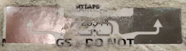
Stripping away the foam covering of the RFID assembly revealed a foil antenna for the 860-960MHz UHF band with the tiny RFID chip at its centre. The antenna is interesting, it’s a rather simple wideband dipole folded over with what looks like a matching stub arrangement and an arrow device incorporated into the fold that is probably for aesthetic rather than practical purposes. He identified the chip as an Impinj Monza 4, whose data sheet contains reference designs for antennas we’d expect to deliver a better performance.
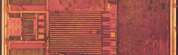
After some trial-by-fire epoxy removal the tiny chip was revealed and photographed. It’s a device of three parts, the power scavenging and analog radio section, the non-volatile memory that carries the payload, and a finite-state logic machine to do the work. This isn’t a proper processor, instead it contains only the logic required to do the one task of returning the payload.
He finishes off with a comparison photograph of the chip — which is about the size of a grain of salt — atop a 1980s 8051-series microcontroller to show both its tiny size and the density advancements achieved over those intervening decades.
Since RFID devices are becoming a ubiquitous part of everyday life it is interesting to learn more about them through teardowns like this one. The chip here is a bit different to those you’ll find in more mundane applications in that it uses a much higher frequency, we’d be interested to know the RF field strength required at the finish line to activate it. It would also be interesting to know how the system handles collisions, with many runners passing the reader at once there must be a lot of RFID chatter on the airwaves.
We’ve featured [Ken]’s work before, among many others in his reverse engineering of Clive Sinclair’s 1974 scientific calculator, and his explanation of the inner workings of the TL431 voltage reference. Though we’ve had many RFID projects on these pages, this appears to be the first teardown of one we’ve covered.