[Sven337]’s rebuild of a cheap and terrible baby monitor isn’t super visual, but it has so much more going on than it first seems. It’s also a how-to for streaming audio via UDP over WiFi with a pair of ESP8266 units, and includes a frank sharing of things that went wrong in the process and how they were addressed. [Sven337] even experimented with a couple of different methods for real-time compression of the transmitted audio data, for no other reason than the sake of doing things as well as they can reasonably be done without adding parts or spending extra money.
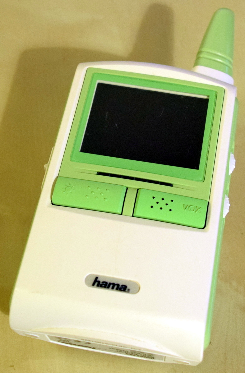 The original baby monitor had audio and video but was utterly useless for a number of reasons (French). The range and quality were terrible, and the audio was full of static and interference that was just as loud as anything the microphone actually picked up from the room. The user is left with two choices: either have white noise constantly coming through the receiver, or be unable to hear your child because you turned the volume down to get rid of the constant static. Our favorite part is the VOX “feature”: if the baby is quiet, it turns off the receiver’s screen; it has no effect whatsoever on the audio! As icing on the cake, the analog 2.4GHz transmitter interferes with the household WiFi when it transmits – which is all the time, because it’s always-on.
Small wonder [Sven337] decided to go the DIY route. Instead of getting dumped in the trash, the unit got rebuilt almost from the ground-up.
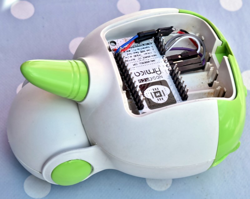
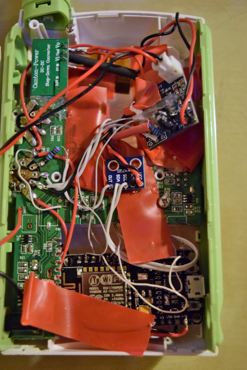 Re-using the enclosures meant that the DIY rebuild was something that looked as good as it worked. After all, [Sven337] didn’t want a duct-taped hack job in the nursery. But don’t let the ugly mess inside the enclosure fool you – there is a lot of detail work in this build. The inside may be a mess of wires and breakout boards, but it’s often a challenge to work within the space constraints of fitting a project into some other device’s enclosure.
The ESP8266 works but is not a completely natural fit for an audio baby monitor, as it lacks a quality ADC and DAC. But on the other hand it is cheap, it is easy to use, and it has plenty of processing power. These attributes are the reason the ESP8266 has made its way into so many projects, including household gadgets like this WiFi webcam.


he makes some assumptions of electret microphones that are way off. no you dont have to amplify it as close as possible to the microphone, and no you dont have to have insanely stable power. I used to run electrets buried in earbuds on a 3 foot cable all the, time I then powered them with a 9V battery (yes over voltage) and ran into a small op amp then to feed a DAT recorder in my pocket for recording bootleg concert recordings. I was getting record quality that was better than most live album releases. by the end of the night I would be at 7 volts on the battery.
They are way way WAY more tolerant than he thinks.
You are, Sir, missing the point. The reason why you need to amplify as close as possible to the microphone is to avoid the 10mV P-P signal being drowned in noise over long wires. Close to an ESP8266 I guarantee that it happens (otherwise I wouldn’t have spent weeks trying to deal with the noise), and the only reasonable way to make it not happen is to ensure that the unamplified analog signal has as little chance as possible of picking up noise, which is achieved by not making it travel far. The 10x amplified signal is much less vulnerable to noise, and can travel a few centimeters, even close to the ESP8266, to the LM358 that amplifies it further by 15x. At that point it’s quite solid, but I still minimized the distance with the ADC so the signal would travel in digital form as much as possible (that is immune to noise). This is to help with radio-induced noise.
As for stability, I’m afraid you are missing the point as well. Whether the voltage is 9V or 7V is irrelevant, what matters is that it must be stable, that is, not oscillate. If the input voltage oscillates at any audio frequency, you’ll get that straight on the output. Unfortunately it’s easy to make that happen with digital electronics, poor filtering, and poor power supplies. It took me multiple tries to get it right and only did the NodeMCU Amica (vs. MCP1702-33 + ESP12F) really solve the problem. This is to help with supply-induced noise.
Both sources of noise are very real and, in my project, were big problems that took some time to solve. You’re lucky you didn’t experience that, because it’s not fun.
Your are both correct. Good RF bypassing on the audio line is a must. Good DC coupling to avoid what we used to term motoroboating – especially with the pulsing PA drain for WiFi.
Doesn’t the ESP8266 have I²S? Seems that’d be easier than sourcing separate DACs and ADCs.
Conceivably, the DAC and ADC should be able to share the SPI port in any case, as one will be transmitting and the other receiving. Some digital MEMS microphones I’ve seen only have the clock and MISO pins exactly for this purpose.
Of course the DAC and ADC could share the SPI wires… if they were in the same device!
A baby monitor has two devices, a transmitter and receiver, and each has either an ADC or a DAC, but not both.
This is not an intercom, but if it was, you would be right (note that if I build an intercom later I’ll use the VS1053 chips). Yes, the ESP8266 has I2S, but I couldn’t find cheap enough ADC and DACs. I always try to buy the cheapest components that do the job, and in this case it was an SPI ADC (good), and an I2C DAC (not as good).
Digital microphones were something I didn’t know about until later in the project, but given their price, I would have used an electret anyway.
The data transfer spec on I2C devices is “standard” of 100kbps or 400kbps but some devices will go to 1mbps, Acquiring an ADC and DAC that do is more costly than those supporting 100/400kbps. Because of bus-state processing, whch requires implementing a state-machine, and the single-channel bidirectional nature of the I2C bus, I am not so sure the ESP8266 can handle up to 1Mbps I2C data xfers while it is processing other tasks.
With SPI on the other hand, most devices can handle 2mbps data transfers and some up to 10mbps. I think an SPI ADC and DAC would provide better performance, faster data rates and lower cost than I2C. Since the SPI protocol requires no bus-state inspection or handling, the processing time to handle the data xfers would be faster. The bus itself has separate tx and rx channels and no buss-state protocols to deal with other than those of the devices. Separate I/O lines can be used to select the ADC and DAC individually.
On the short wires from MIC to amp, unless the MIC is “balanced”, which the low-cost electret are not, there is little noise immunity from the internal clock interference sources of the ESP8266. You can 2/3 and 1/3 rail bias the electret MIC element but it requires a higher voltage source to do so. 3.3 volts may be too low but I do not know off hand without looking at a datasheet. As you stated, you already found this out. Empirical data always trumps theoretical data (unless the measurements are flawed in some way).
Sven337, I admit that i did not fully read your project post.but did you have difficulty sourcing a capable and low-cost SPI DAC for this project? Is that why the I2C DAC?
There is always a sense of accomplishment when one runs into unanticipated design obstacles and figures out how to resolve them, bringing the whole project to fruition. Nice job!
Peace and blessings,
Johnny Quest
Just read the project page. Very well thought out and detailed. Thanks for sharing!
I see you are using peripheral “modules”, which makes interfacing easier. For future reference, the TP3054 CODEC, posted below by “Redhatter (VK4MSL)”, might be a good fit for this type of project. You would likely have to make your own breakout board to use it.
Peace and blessings,
Scott
One big issue with I2C on ESP8266 is that the ESP8266 doesn’t actually have hardware I2C. It has hardware SPI, but for I2C you need bitbanging. I have read that it was possible do 800kbps I2C, if you overclock the ESP8266 to 160MHz. I’m running the DAC at 400kbps and it works well, but the latency starts to get significant for 50us per sample (I measured it but can’t find it any longer).
So just because of that, SPI is superior.
I had difficulty sourcing a capable low-cost SPI DAC, yes. Don’t ask me why, but the I2C one was easy to find and cheap. Perhaps I didn’t look hard enough – it does get kind of boring to spend hours and hours trying to source a cheap chip, and honestly I had not anticipated that an I2C DAC would be so annoying. Truth be told, it’s not that annoying: everything works perfectly and there is room to breathe in terms of CPU cycles. But it does consume more CPU time than my engineer’s sense of elegance is happy with!
This project has been an emotional rollercoaster. I did learn a lot, but the hard way. It was not fun to sink however many days I spent in the analog circuitry, to finally realize that I had to start over. But at least when I started over I did it well on the first try and quickly, and when it finally worked as expected that was extremely rewarding!
Sven337:
I’ve got a few ESP-12’s and started to work with one but got distracted by another project.
I mostly work on ATMEL AVR’s, all flavors. There is a power-saving “sleep” instruction that can be executed and hardware interrupts can “wake” the processor from sleep. This feature is wonderful for designing low-power battery operated embedded devices. I do not recall if the ESP-8266’s ARM core supports this type of power-saving feature, nor if LUA supports it.
Peace and blessings,
Johnny Quest
@Johnny Quest
Sleep modes on the ESP8266 deserve an article on their own. There isn’t as great a sleep mode as on most AVRs. Instead, you have “automated” (call behind your back by the SDK) modem sleep (= transparently disabling wifi) and light sleep (= not very transparently sleeping the CPU, AVR-style). These give you some savings, but to go really low you need to use deep sleep, which shuts down the CPU for good, and resets it after the given delay. Deep sleep latency is pretty big, around 5 seconds from sleep to “wifi is ready again”. That’s not usable for this project, as the transmitter needs to constantly read the ADC (to decide whether to send sound or not), and the receiver needs to constantly listen on wifi (to play sound when it comes).
Instead, my babymonitor uses modem sleep, or light sleep, I can’t remember. It’s not battery powered so not very important anyway.
(By the way, the ESP8266 isn’t ARM, but Tensilica lx106. And you don’t have to program it in Lua, I program it in C++ using the excellent esp8266-Arduino)
>sending twenty thousand samples per second to the I2C DAC with an ESP8266 does consume a lot of CPU time
reuse i2s to emulate i2c
i2s codecs are big and expensive, no point using 40pin qfn just for one mono channel
>It is not possible to use MP3
there are esp projects using fixed point mp3 decoders (without overclocking), encoding would be more problematic tho
but something like Codec2 should fit, sadly still no fixed point implementation after 6 years
You’re welcome to contribute a fixed point implementation if you think it’s so easy. I’m not sure it’s such a good fit for this application for two reasons:
1. it’s a voice codec, better suited to getting speech across where bare minimum fidelity is required.
2. IP traffic overhead makes anything sub-8kbps a waste of time.
Speex or Opus would be better options.
As for I²S: http://au.mouser.com/Semiconductors/Audio-ICs/Audio-CODECs/_/N-bjzfw?P=1z0z63x&FS=True
This is a one-off hack, not a production line, to me those aren’t expensive options. :-)
The TP3054 is an old (circa 1994) but adequate part to use. It has a built-in input gain amp with external connections for gain selection, which may have been able Sven337 to reduce parts count.. It also directly support u-Law and A-Law compression algorithms.
Nice find!
Peace and blessings,
Johnny Quest
Would Speex or Opus actually be a good choice. They are designed for speech but is a baby crying close enough to speech for it to work well?
Hi,
You did an amazing job. I was looking for exactly this this. Few module alternatives I have thought off.
I made a mic preamp (with a primary amp phase using 2n3904 along with the subsequent level using lm358) that works well. I used this preamp with Arduino ADC A0 pin, recorded the samples via usb serial @38.5 khz using isr based adc readings, and the recorded audio was real good. So I was thinking to use Arduino as the ADC as well as the DAC using resistor ladder technique. Once I get the samples from arduino at esp end, I can easily transmit it over. Can you suggest whether with approach I would reach somewhere?
Also can you suggest suitable wiring procedure between Arduino and ESP. Should I use the serial interface of both devices or use SPI communication between these two, I believe in case of SPI the arduino would act as slave.
Kindly put some light on these thoughts.
Thanks in Advance.
Debojit
Well, I wouldn’t advise using the Arduino as an ADC/DAC. The simple reason for that is that building your communication protocol between the Arduino and the ESP8266 is harder (since you have two sides to implement) than using a ready made external ADC or DAC chip and following the datasheet. So to the best solution is to go my route and not use an AVR, in my opinion (that is why I didn’t use one).
If you insist on using an AVR, use SPI communication, and make the AVR the slave indeed.
Thanks for your comments.
Can I use a module having both ADC+DAC on same module like http://www.ebay.in/itm/PCF8591-AD-DA-Converter-Module-Analog-To-Digital-Conversion-4pin-F-F-Cab-KG191-/112033205913?hash=item1a15b30e99:g:FFsAAOSwnNBXbM3l
The spec says the transfer rate/sampling rate in only limited by I2C speed, now I believe esp has got not h/w based i2c and only s/w i2c. Can you please check and confirm whether this module can process data at ~ 30-40 khz.
Thanks,
Debojit
I do not think that this module is a great choice. A quick look suggests that it’s 8bit only, and I2C only. Both are issues. You might be able to sample at 40KHz, but it’s still going to sound bad due to the 8 bit sampling.