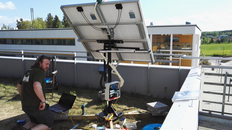
[Bruce Helsen] built this dual axis solar tracker as one of his final projects for school.
As can be experimentally verified in a very short timeframe, the sun moves across the sky. This is a particularly troublesome behavior for solar panels, which work best when the sun shines directly on them. Engineers soon realized that abstracting the sun away only works in physics class, and moved to the second best idea of tracking sun by moving the panel. Surprisingly, for larger installations the cost of adding tracking (and its maintenance) isn’t worth the gains, but for smaller, and especially urban, installations like [Bruce]’s it can still help.
[Bruce]’s build can be entirely sourced from eBay. The light direction is sensed via a very clever homemade directional light sensor. A 3D printer extruded cross profile sits inside an industrial lamp housing. The assembly divides the sky into four quadrants with a light-dependent resistor for each. By measuring the differences, the panel can point in the optimal direction.
The panel’s two axis are controlled with two cheap linear actuators. The brains are an Arduino glued to a large amount of solar support electronics and the online energy monitor component is covered by an ESP8266.
The construction works quite well. If you’d like to build one yourself the entire BOM, drawings, and code are provided on the instructables page.


So I am wondering, whats the cost of this sort of thing? I don’t see a full price list. Has it come down in price?
a while back i saw a concept by an Israeli company that had a bunch of motorized mirrors focusing the sun on tiny panel (~100cm²) and claimed power output in the hundreds of killowatts range from combined photovoltaic and thermal energy from the one cell. Of course i can’t find it now with all the BS on youtube and the inability to search through history or liked videos.
Anyway, i wonder why we don’t see more motorized mirror setups to drop more light onto existing solar panel installations.
this is called a heliostat.
Photovoltaics do not like elevated temperatures. Someone here can explain it, but heat kills efficiency. Heliostats usually work by storing the energy in the form of heat. one I read about used molten salt (NaCl) to make steam to drive turbines.
@GYRE
Look at following topics: concentrator photovoltaics and thermal (CPVT), combined heat and power solar (CHAPS) or hybrid thermal CPV
The light sensor part is redundant as you can calculate where the sun will be if you know the time and your location. The ESP8266 would have access to a NTP server and the location does not change. Basically all you need is a simple lookup table and the current time.
I could see the light sensor being useful up here in Alaska during the summer at a cabin. LTE, 4G etc is very well poor up here.
You can just use a realtime clock module, or GPS for time, even the $2 RTC is probably accurate enough.
One time I saw a solar cooker. It had about 10m² of mirror area and was tracking the sun with a pendulum-clockwork. It had to be aligned so that single axis tracking was sufficient (the axis has to be parallel with the rotational axis of the earth) and you had to wind up the weight in the morning.
You do not need ultra-precise motion for solar tracking.
Yeah, I was thinking of this same idea.
It would probably save power too, as it only needs to wake up every X minutes to move the rig then it all powers down again. I think there is a Perl module that will give you the functions needed to calculate the LUT, otherwise there is C and C++ code out there to do the same.
That’s really depending that the open loop mechanical system is accurate, no slipping and not moved by wind. A feedback mechanism can try to correct the errors and get away with brush motors and cheaper mechanism.
Now the tricky part is that you need to calibrate or account for variation of between the 4 sensors vs light intensity. Those sensors aren’t exactly parts with tight tolerances.
You’d have to engineer it very badly to be less than 5% accurate or whatever fairly gross tolerance are relevant, this will depend on the characteristics of the anti-reflective coating on the cells. If you are still within the capture angle range a misalignment will not matter. You can use this knowledge to step the rig only enough times to stay within the spec and therefore minimise power consumption as the MCU shuts down everything until the RTC wakes it up again. The ESP may be able to act as a RTC for the motor driving MCU, even that can still measure a voltage on it’s ADC in low power mode so long as the WiFi is not transmitting. The bottom line is that what you do in software will determine if the effort of moving the panels is worth it at all.
Calibration only needs to be close enough. A few degrees off on the orientation doesn’t make a significant difference, and the shield between the quadrants insures that there is a significant difference in intensity: 1:4 or better on a clear day, and as the haze increases, and the difference drops, it becomes less important.
If it were me, and it isn’t in this case, I would use both tracker and RTC, and use the RTC for rough position, the tracker for following, and use the tracker to keep the RTC close enough, which is pretty much within an hour or so. Then the math is a lot simpler, as no horizon corrections are needed (the tracker handles it), and the RTC can deal with things when there are clouds or too much haze for the tracker to follow, so when things clear, the panel is close enough for the tracker to lock in quickly.
But the point is that the RTC and lookup table is both simple and so accurate that the tracker is pointless, it takes more parts, which could fail and uses more power. You don’t even need 2 MCUs, just the ESP should be able to record power output in low power mode, then wake up periodically and realign the array while it is also sending the collected data before going back to low power mode. Remember this project is only worth the effort if you can find the best trade-off between the extra power required to operate it and the extra power generated, then you have to also factor in initial cost, of parts, and the reduction in reliability that things like light sensors brings. All it takes is one bird turd to mess up a light sensor.
You’re missing the point that the RTC solution still requires position feedback (panel vs earth) in order to go to the required azimuth/elevation. That position feedback incurs similar costs as the more-direct approach of taking panel-vs-sun feedback directly
I did not miss the point, the point is bogus. I have assumed that there are stop switches to ensure the rig can’t burn out it’s motors, so every dusk the rig drives back to the “zero” position then move forward to face the next dawn’s location. The zero position is just any point you set that is outside the maximum required range, it isn’t actually zero. My method works with no extra parts (in fact less) and operates periodically so it’s power consumption is minimised. Unless you are suggesting that a real installation would not use end-stop switches? If you can do it in software you should not use a hardware solution, because for a given level of functional complexity hardware is always less reliable. Sure the entire processor could die, but that will kill the tracker anyway and watch dog timer interrupt routines ensure the MCU does not lock-up due to a random bit flip.
Also because of the feedback mechanism, the mechanical arrangement to move the panel doesn’t even have to have a linear relationship. You don’t even need to worry about exact orientation/location of your panel. That alone could simplify the cost, design and deployment of the system.
BTW solar tracker is a classic example of feedback back before microcontroller, An opamp could have done the feedback circuits without the fancy power management. Speed isn’t an issues, so very low power opamp could be used.
What does it do if a bird poops on one of the sensors, keep tracking off to one side until it trips a stop switch, or burns out the motor etc.?
Even with you look up table, what happen if a squirrel were to chew off your wires or that you cheap motor burns up. Or that birds shits on the system eventually cause corrosion in your rotational system.You list is BS because you assume that yours will work which isn’t the case. A open loop in an uncontrolled environment isn’t exactly safe either.
Nothing is safe. Deal with it. Figure out the failure modes and find out if it is critical in the first place.
Design something for reliability by reducing your FITS and increase the MTBF. Between electronics, mechanical and firmware, I would say mechanical, environmental and firmware are the most likely cause of issues. Between a complex uC + ESP8266 wireless link vs an opamp, the opamp is the more reliable system.
Monitor the motor current, solar panel output and look at the trends. That should give you some expect values and figure out if something is starting to fail.
Nice rant bro, LOL, what open loop? I have the power output of the array to tell me if I have moved off target or if there are other anomalies, in fact I can track the sun just by scanning the array about and watching the power output, if my code is sophisticated enough to not go into oscillations due to passing clouds etc. i.e. I don’t even need the RTC or sun path table if have an adaptive scanning algorithm. You know you could have pointed THAT out, if you knew about it….
Look at “Serge” what a childish little brigader.
Here is how it works “Serge”, you say what you like, there is no wrong or right, there is just new logic and facts to share, or in your case repetitive and useless bullshit.
Don’t bother talking to this guy tekkieneet. Dan is one of those people that thinks their opinion is the only correct possibility, and will not stop arguing until he has the last word.
You are not his mother, but you are a liar.
Wow. This went sideways unnecessarily.
Anyway, I wanted to chime in here because I have experience with both systems. I’ve actually built both types a few years ago. There are pluses and minuses to both, but honestly the sensor based system is better. It compensates. That’s really what it’s all about.
If you plant it on uneven ground or out of alignment, if there’s a tree or tall structure in the path (every panel on my property has a tree in the way at some point in the day) it’ll aim toward the source with the most light, it’ll adjust for clouds and in low light output weather you can get it to park, it’ll even adjust to gain the most from surface reflections off windows or water. Real world stuff that make the mathematical model a bad approximation of what a solar panel will experience. Plus it’s just plain easier to execute from a programming perspective because all kinematic modeling of the panel movement disappears. No data connection is necessary either (although I’ve found being able to communicate is a huge asset in order to park the panel for high winds or to prevent snow accumulation). A sensor system just sorta works. You can also use much cheaper actuators because positional feedback is not necessary.
Anyway, that’s my opinion based on personal experience. I have the code for a PIC chip if anyone would find it useful for their own projects.
Unfortunately while extremely cool, I have retired all of the solar trackers from my system due to the lack of robustness. I have static solar arrays that have run for years with no intervention, but tracking arrays always seem to get beat to pieces by the elements. Those actuators CLAIM to be waterproof however that is absolutely not the case. Their internals corrode and seize. A hurricane flipped my last tracking array. There’s no real way to prevent wind from getting under the things, whereas on a flat roof that is not the case.
On a side note, how have you been with regard to hail storms, PV owners never seem to want to talk about that topic. I’ve heard that the German units are tough enough but most of the stuff that is cheaper and from other places will not survive. Have you got the array insured? If so what overhead does that add to the array costs over it’s life?
I just realised you can also eliminate one drive motor by having a two way ratcheting system at each end of the travel range for the day arc. The MCU just drives past that point and clicks it up or down one angle according to the date so as to track the sun position for the next day.
Yep. I design solar trackers. Tracking the sun via calculated sun azimuth and altitude involves some interesting formulas but is far more reliable over light sensors as they are prone to dust and bird crap.
We have 500kW trackers in field already with another 5 MW in the next few months. Dual axis with PV is not really cost effective in large scale. Dual axis only makes sense with thermal systems.
The light sensor will keep the sensors pointed at the *brightest* part of the sky though. It’s no use pointing your panel at where the sun should be when it is obscured by a big dark rain cloud.
Not very effective with the sort of cells that need directing anyway, that is the point. They do not handle diffuse light due to clouds very well at all, unlike amorphous cells. I think you will find that the brightest part of the sky is where the sun is anyway, within the number of degrees range that are relevant. What you suggest would have the array sweeping around madly for little extra gain and a big loss of power driving the motors so actively.
Anyway I have already pointed out that you do not even need a sensor, as the PV cell power output acts as one! If you could make such an active array power efficient (debatable according to the commercial power guys) you would start with the calculated sun position then spiral scan outward from that position to optimise the output. Ta Da! The best of both worlds. That is the whole point of using an MCU like the ESP8266, it is so advanced that you can pack a lot of intelligence into it and this lets you reduce your component count drastically, which reduces costs, boosts efficiency and lowers failure rates.
Somebody else mentioned a passive system using a pressure tank, if you can get that to cover all of the same contingencies, only elegantly simple solutions like it can out perform a well programmed MCU. I’m not code zealot, I actually prefer the beautiful minimal mechanical solutions, when they actually work better.
Re: your question above about PV panels and hail storms (the reply option isn’t there under your comment). My panels were manufactured by BP Solar when they still manufactured in Australia. The panels and mounts must be cyclone-rated to be covered under house & contents insurance (no additional premium for PV systems, as far as I can tell), and they are also rated up to a certain size of hail (golf-ball, I think) up to a certain impact speed. I’ve got the spec sheets buried away somewhere, but these are some of the reasons I bought relatively expensive PV panels instead of cheapies. Also the warranty – 80% of rated power for 25 years.
I guess you really do get what you pay for. I saw one recent story where the panels held up rather well, the only problem was they caused the entire roof to peel off in the wind when normally a tiled roof will just blow out a few tiles and equalise the pressure differential. Oh man that would have hurt, coming home to that mess.
Yes, size and speed, there are standards for both solar panels and solar heat tubes. But there all at sea level! Altitude increases hail’s falling speed due to a reduction in drag. Where I live (1800m above sea level) we have about 14% less atmosphere than at sea level. Lower pressure, lower drag, more speed. In addition the energy formula (0.5 mv^2 ) has a square in the velocity. So how much more energy does a 2.5cm piece of ice have at 14% less air? Not sure, but my gut says 45 – 70%.
Um, no.
A lookup is nice, but then you also need to know where the panel is pointing. So you need positional feedback.
With a sensor looking at the sun, the sun is the feedback. While the sun is lost behind some clouds, a large moving average filter can provide the approximately the speed you were traveling at over that last couple of hours, you can simply drift along until the sun comes out full force again. As for the optical sensor, one can even use a camera looking at the sun through an appropriate filter, they’re super cheap nowadays. For the resolution you need, and the massive contrast available, you could even tie at the composite video signal of a cheap camera straight into a micro’s pin. Or what about the super low res of an optical mouse?
If the aim is to point the thing at the sun. reference it to the sun. All the lookup tables in the world wont help you when someone bangs into your mounting poll and pushes everything out of alignment. A sun looker will however compensate instantly.
The power output is a sensor so you don’t need a separate sensor to catch anomalies.
My thoughts exactly.. A lookup table is so much less complicated and expensive and a single axis is of course even easier and probably not a whole lot less productive.
Damn, it’s really too bad he didn’t do a side by side comparison between his solution and a standard panel with a fixed position… I’ve been wondering for year if it’d be worth it.
This is the most scholarly work I was able to find quickly, http://www.enggjournals.com/ijet/docs/IJET13-05-02-213.pdf
But most of the retailers of solar trackers cite 30% increase in efficiency with single axis, and another 10% for dual axis. You can do quite well with a single axis azimuth tracker and manually altering the altitude angle a couple of times a year.
This is timely work, I am currently building some small “off grid” boxes to take “glamping” and wondered if some small tracking panels to keep it topped up were easy enough.
I think there is also a loss they did not account for as the light red-shifts at lower angles. Also a fix and moving system will be equally efficient at least once a day (assuming the day of year alignment is correct) for the same reason that a stopped clock is correct twice a day. This fact undermines the credibility of ” Fig.4 Simulation Result for Comparison of Fixed mount and Single-Axis Tracker System”
The design would be better suited for landing on any other planet as it treats the sun as an unknown rather than it’s clock-like familiar way of passing. A motor and a weekly bump for elevation is all that is needed. A clock motor could be considered a computer, but none is needed.
Unless you believe in pole shifting conspiracy, the sun is going to rise in the expected place.
The writeup about his article is pretty deceiving. He didn’t use those actuators provided in the link. Furthermore, I believe those actuators would be quite inappropriate for this task, as they seem far too weak. I should know I made one.
Calling shens, observed sun for 2 full nanoseconds, didn’t move. ;-)
Slacker. You better modernize your measurement instrumentation. The sun moves an apparent distance of 20 millimeters in 2 nanoseconds. An easily measurable quantity.
the current house I live in once was fully off grid. The previous owners installed a passive tracker. I never observed it working and when I spent some time Investigating how it worked, I accidentally picked off the rust blister that was keeping the methyl chloride what ever gas inside :)
The passive tracker I have is made by zomeworks.
I would do it injustice to try to explain how they work, but it seems kind of like a big tippy bird.
The passive solar tracker with a gas cylinder heated by the sun until the panel moves to shade it has worked fpr over 50 years now, and resets every night when the cylinder cools down.
1 moving part, and it is the piston.
or, you could put 4 small solar panels that power the az and el motors directly. wire the top and bottom one in parallel, but with alternating polarity, and put the elevation motor parallel to them. same for left and right and azimuth. dont forget to include sime current limiting resistors in series with each panel.
sure, this only works if the array is small enough for the motors to be powered by the sun directly, but we already established that this doesnt really work out, economically speaking, for large arrays.
besides, if you really want to do it on something larger, i bet you could replace the motors in my circuit with some transistor based current direction sensing device that would then move the motor from a stored energy source.
https://www.youtube.com/watch?v=HkhVomoD47g
That is a nice design, how do you balance it when each cell’s efficiency is a little different from each other?
i dont believe they vary sufficiently for this to matter. but since my beliefs are irrelevant, to be honest, i guess you could calculate some resistors/potientiometers in series with the panel.
motors are current devices, so the most minimal amount of limiting would probably work.
i immagine that the resistences would be very small….
That is a cool idea, simple and notably analog. I have seen it a while ago and did a prototype on my own. Works like a charm, beautifully, efficiently and most importantly extremely reliably. As you have mentioned it is a simple and a highly efficient design.
Flash: Hipster makes tracking solar panel, break-even period exceeds projected life-span by 30 years, Hipster gets big Government tax break anyway.
You people obviously know more about solar than I do…
Why don’t more arrays use a ‘microlens’ in front of the panel? I can’t tell if it was just a marketing scheme or if it actually works.
Yeah holographic concentrators are a thing, they are advantageous if you can get more efficiency out of the cell at higher than natural luminance levels, and or if you wish to split the light spectrum so that different sub-cells, with optimal band-gaps, are illuminated with matched light frequencies.
I think for permanent installations, tracking based off a look up table would be the most efficient – you would only have to power the motors at set time intervals and move to known positions. With the tracker I fear situations where a temporary reflection off something or temporary light blockage could cause the panels to move erratically. Unless the control loops were written VERY intelligently, I don’t see how the tracker could adjust the panels more efficiently than an open loop system that uses a lookup table.
Where I see a tracker being very useful is in high end RVs, mobile command units, etc. When the rig is parked, simply activate the tracker, and call it done. The tracker would account for the vehicle being at any location, pointed in any direction, and parked on uneven ground.
Yeah that would work, if there was no GPS data available from the RV, otherwise the sun position can be calculated on the fly. I am familiar with this as I was part of a team that implemented it in a 3D package to simulate natural daylight, the only inputs you needed were location and time, the code did the rest. Unfortunately it is in C++, but I believe it was derived from US Gov code written in C so I could dig it up for anyone who is interested.
We are talking about a trivial amount of code for even an ESP module to handle. Keep in mind that you could also have code in an App running on a mobile phone that just updated the MCU’s lookup tables when you were “setting up” at a new location, using the same WiFi link that the modules used to report it’s status and power output etc.
I agree that it could be calculated on the fly, but you would also need more than just GPS data. You would also need to know the orientation of the parked vehicle (relative to true north), and a 2 axis tilt sensor to know what your baseline tilt is. After adding in a compass sensor and a 2-axis accelerometer for measuring baseline tilt, the simple lookup table approach becomes a bit more complicated by requiring the resulting angles to be augmented by data from the vehicle orientation and tilt sensors. Suddenly the light sensor approach seems a little simpler.
I have 2 solar panels mounted flat on my RV roof and I am definitely not about to add a complicated bulky solar tracker of any kind. If I need more off grid power for my weekend toy I’ll just add another panel or two. I was simply trying to think of possible applications in which a light sensor driven solar tracker would be advantageous over a “lookup table” driven solar tracker. The cool thing about the project owner’s setup is that he could log the angles his light sensor driven setup moves to, and later compare those to calculated/theoretical angles. It would be interesting to see the deltas.
A fun and insightful contest could involve distributing identical panels to different groups using different tracking methods and running them side by side, and seeing which setup collects more photons (after power used to drive tracking motors deducted of course). Id be curious to see how the tracking systems would compare to a non tracking panel setup that was simply aimed at the “average” position of the sun.
“but you would also need more… ” all that is on most phones these days, you could even use the sensor data on the phone just to help you park your RV at the best angle to make the most of a simple tiltable panel set on the roof. They would be flat for travel and then have their back edge raise when you park.
You can also cheat with a single panel by adding mirrors, so you had better put that in your contest rules. :-)