One of the most common problems in the world of microcontrollers is running out of resources. Sometimes it’s memory, where the code must be pared down to fit into the flash on the microcontroller. Other times, as [Fabien] found out when he ran out of pins, the limitations are entirely physical. Not one to give up, he managed to solve the problem by using one pin for two tasks. (Google Translate from French)
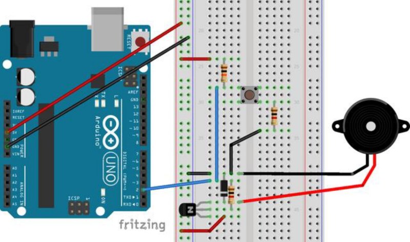
During a recent project, [Fabien] realized he had forgotten to add a piezo buzzer to his project. All of the other pins were in use, though, so his goal was to use one of the input pins to handle button presses but to occasionally switch to output mode when the piezo buzzer was needed. After all, the button is only used at certain times, and the microcontroller pin sits unused otherwise. After a few trials, he has a working solution that manages to neither burn out itself nor the components in the circuit, and none of the components interfere with the other’s normal operation.
While it isn’t the most technically advanced thing we’ve ever seen here, it is a great example of using the tools at your disposal to elegantly solve a problem. More than that, though, it’s a thorough look into the details of pull-up and pull-down resistors, how microcontrollers see voltage as logic levels, and how other pieces of hardware interact with microcontrollers of all different types. This is definitely worth a read, especially if you are a beginner in this world.


This is an old technique, it’s called Charlie plexing for those how are interested
Barely fits the definition…
Negative. True it is an old, tried and true method of multiple pin use.
But not charlie plexing.
Charlie plexing is for multiple OUTPUTS only, specifically LEDs (the diode nature of LEDs are a necessity of CP), and is a relatively “new” term.
This is within the spirit of Hackaday. It doesn’t necessarily need to be something complicated, or even different. Some of these simple methods can be expanded and used for other things. I don’t mind this stuff at all, and it is applicable to some of my projects. And making it more complicated with a MUX isn’t always needed.
This is new to me so I appreciate it. Everything is new to everyone at least once, after 40 everything is new a few times.
You don’t have to stop there. You can have two diode matrices in reverse directions and have 18 functions from 6 pins (3×3 = 9 .. x2).
Also – do you really need a reverse biased diode for a piezo? I can’t imaging more than 0.6 Volt bouncing back from a piezo!
I think the dioide is placed across the piezo not inline.
I am guessing the purpose is to limit the volume of the peizo?
It’s in parallel with the piezo *and* reverse biased like you would have with a relay to stop a back EMF coming back from the relay coil.
Fair enough a piezo works in reverse and will convert kinetic energy to electrical energy but I would expect the reflected voltage to be so small that you wouldn’t need to worry about it. The diode isn’t going to shunt any voltage until it get to -0.6 Volts or so.
Reminds me of a product I once worked on, where scope creep nearly killed us. The one button input became two button on the one pin, then became two buttons on one pin with external button removal detection, which then grew to include voltage rail measurement.
And not an A2D in sight – all with on board comparators and cleaver use of external resistors…
I often use MISO, MOSI, SCK and one extra pin as the 4 data pins for a 2×16 LCD and the ISP header. Each peripheral gets their own chip-select pin to insure they don’t screw with each other. Even the ISP header has an implied “chip-select” in that it’s only active when !RESET is low.
Regarding RESET, I often use it as an input without changing fuses to disable the reset functionality (and thus breaking the ISP). Protip? Memory is preserved during reset.
So if your program/logic allows for it, your main entrypoint can also be thought of as a label that’s been GOTO/JMP’d to when reset is pressed(low>high). e.g. add a counting variable to use for changing modes.
If using avr-gcc, you need to add a “__attribute__ ((section(“.noinit”)))” to the variable declaration(s) so gcc’s init function doesn’t zero them out on reset.
Oh yeah, and for multi-SPI slaves, unless you’re sometimes running some in parallel for some reason, I like to use a demultiplexer to cut back on the CS pins. i.e. a 74138 uses 3 pins for 7 devices or 74154 for 4 pins to 15 devices (one of the output pins is unused for a “no CS selected” state)
If you think like that then you would be very good at a Hardware Definition Language. Your solution is closer to n = 2 ^ bits.
I sometimes use the power led pin, high to light led, low to drive buzzer. Most of my stuff the power led is actually carrying diagnostic pulses, looks like a solid led, but on a scope lots of pulses that show timing of different segments of code
That’s a hack in itself!
+1 Internets for you Sir!
I often have a Power and a Status LED(s) – Power is usually fixed on and use the status led for debugging.
I now will adopt your excellent approach!
I do it in a similar way, only lazier: i just use the power led on the UART TX and no buzzer.
I’ve done this a few times too, I usually do a bit banged pin when I need the uart elsewhere, but I mostly want critical timing so that’s when I pulse the power led, or vice versa , the power led is on and I pulse it off in various routines so I can measure timings
I almost always do that in debug mode, but never thought of incorporating that same functionality into the end device. That’s brilliant.
Well, the best solution would be a debugger :)
Otherwise in big projects the code for the led would end up in a messy debug which works, but after 2 months if you look at it, you could never understand the why of the pulses. My 2 cents…
I was waiting at a train crossing and a train had passed but I was checking if one came form the other side too. I then thought to myself ‘you can get military spec micro controllers for $1.25 and there is still no indication at crossings what direction and how many trains there are’. Seems all very old and primitive.
That and they still did not widely adopt my idea of putting LED warning strips next to the tracks on a crossing for bicycles and pedestrians to give a visually connected warning of the location of the danger. I only heard about such use sporadically on normal crossings for people who are engrossed into their pones and don’t look up.
Sometimes society is very very slow.