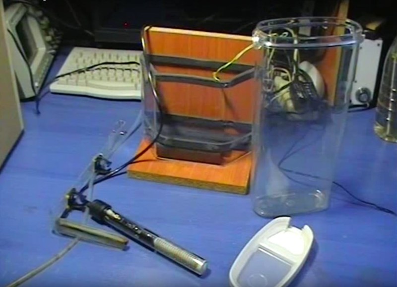
Most circuit boards any maker could need for their projects can be acquired online at modest cost, but what if you need something specific? [Giorgos Lazaridis] of pcbheaven.com has designed his own etching bath complete with a heater and agitator to sped up the process of creating your own custom circuit boards.
[Lazaridis] started by building a circuit to control — in a display of resourcefulness — a fish tank heater he would later modify. The circuit uses a PIC 16F526 microcontroller and two thermristors to keep the temperature of the etching bath between 38 and 41 degrees Celsius. The fish tank heater was gingerly pried from its glass housing, and its bimetallic strip thermostat removed and replaced with a wire to prevent it shutting off at its default 32 degrees. All of it is mounted on a small portable stand and once heated up, can etch a board in less than 10 minutes.
Click here to check out how he designed the control circuit, or here to see how he modified the aquarium heater to suit his purposes. Or, you could always use a 3D printer to etch your board instead.
[via Christopher Mayhew and PCBHeaven.com]


Interesting, I was etching PCBs in my head the other night, due to wanting to think of a way of doing small PCBs without much etchtant being poured out….. I was thinking of ziplock bag and “boil in the bag”.
Disclaimer;
Etching boards in your head is probably not recommended.
/joke
On the other hand: if you have enough room in your head to etch PCB’s you can’t do much damage
Well obviously it’s in my mind palace…… in the basement…… sublevel 6.
Mine only goes down to Section 5, because I got distracted by the Artifact before I could build any deeper…
I often worry about the quantity of etchant I use- how small a qty f etchant can you get away with. I’m guessing the etchant becomes saturated with copper at some point and losses its effectiveness.
Etch in a bag kit
https://www.megauk.com/etchants.php
If you’re using copper 2 sulphate you came “refresh” the tank with some H2O2 and the occasional dose of HCl, which is much easier than Iron-based enchants to handle, although care must be taken not to dump it into waterways (much like any etchant)
When you have an air-based agitator, the need for H2O2 is reduced (free oxygen) but you still have to dose it with HCl (“muriatic acid”)
Of course, for the real bootstrapped out there you can probably make this with (essentially) nothing but copper clad PCB, air agitation, and certain bodily secretions, although I’m not sure if the Sodium and Potassium salts poison the copper cycle.
The link I refer to when making the stuff;
http://www.instructables.com/id/Stop-using-Ferric-Chloride-etchant!–A-better-etc/?ALLSTEPS
I did not know this one and none of my colleagues and friends did either…so hats off to you, sir for providing the link. Seems a very interesting way to do things, if a bit dangerous (due to HCl) but will definitely try it.
To misquote the title of that Instructable, “stop using HCl etchant!”. Ferric Chloride might not be the nicest chemical in the world but is *far* better than hydrochloric acid. The fumes can rust everything in your workshop and are very bad for you.
Of course, if you are using it along with toner transfer for your Arduino shield then go ahead. It’s already to late for you.
But hey, if your determined to self destruct – nitric acid has a stronger reaction to copper than hydrochloric acid. just be warned! it also has a much greater reaction to flesh as well.
Come on, hydrofluoric acid is where it’s at!
@Generic Human: why buy a plastic container when i have a perfectly good bath tub?!
Totally true. All the processes based on HCl are shit for hobbyists. The fumes corrode everything in the whole room!
Right, mayyyybe if I wanted to go limited mass production, I’d do that and fume hood it.
Where does the Cu sulphate come in? all I read there is Cu chloride.
You don’t need all this crap. You just need a sponge and it is a much faster process using a minimal amount of etchant. You just wet the sponge with etchant and rub it over the board. It works great.
Wow, that contraption must use mega amounts of enchant! I etch flat and use about 3mm of enchant or 100ml or less for the boards I do here. They also take less than 5 minutes to etch. I am using Ammonium Per-sulfate at about equal parts dilution and at 70 *Celsius. I should add the my PCBs are minimum etch layouts.
| “Most circuit boards any maker could need for their projects can be acquired online at modest cost…”
That’s great for multiple copies, but if you just need one board, it is much quicker and cheaper to just etch your own. Not to mention the often overlooked feeling of self-accomplishment that so many of the newer generation are missing….
I agree, if you go straight to the board house without prototyping first then you will end up with 10 copies of something that doesn’t work and you would have lost a lot of time as well for people like me that are far away from bard houses.
The trick with going to a board house is to be within simple rework range of the desired target. At least for relatively low frequency designs, checking the schematic and board layout should get you within a few cuts and additional wires of a perfect board (ok, the last board I did, I managed to pick up an incorrect pinout of an LF13331 somehow, so I had 8 cuts and 4 wires). Think of the board as a close approximation of what you want and don’t beat yourself up if you have to add a wire or two.
The ‘get 10 boards’ thing works well for doing music synth, where you need multiple oscillator boards, multiple VCAs, multiple filters and multiple mixers. I designed boards that had a dual VCA plus a bit of extra space used for a ring mod. Only one board got the ring mod populated. I have now got it off to an art to design a board that has multiple purposes and gets populated accordingly. A digital VCO for instance has both a single output from a PWM, or multiple outputs with an optional i2c DAC.
I deliberately designed a 16×16 BLM with a set of 9 96mm square boards (less than 100mm x 100mm being the price point) each with a 6×6 array of pushbuttons and LEDs. I got my 16×16 matrix, a space and an extra column and row for controls. I managed to do that without any rework required at all. It’s a bit easier getting it right with a replicated array. Or very very wrong. OK, I admit it, I would prototype if it were easier; I could then just churn out the board and let the electronics do the testing.
Looks like the fish are going to have to move out, so I can have a go myself.
The good stuff is at pcbfx.com they also list it on ebay. Have a look at their Toner Transfer Paper (actually dextrin) and their Green Toner Reactive Foil. You may not need these later but start with the good stuff while your getting used to the process. These bits will get you down to 5mil traces once you get used to it. You need a laminator (perhaps modified). There are good examples on HAD.io You could also use a chemical fusing method from here (I haven’t tried this yet) http://www.instructables.com/id/Heatless-cold-Toner-Transfer-for-PCB-Making/
If you use these products the the quality will come down to toner (more later) and the temperature regulation and speed of the laminator. A normal unmodified laminator goes too fast so you have put the board through 6 – 8 times and that causes a little smearing.
Toner is make or break. Some toners just don’t work at all so do some research about what does work if you are going to buy a laser printer. Apparently Brother printers give the most trouble.
I had a look at your projects and yo get to make some really cool stuff.
PS: I am not associated in any way with pcbfx
My etching bath looks very similar to this wooden stand, _without_ the tall container. My back plate is a think aluminum plate covered with a thin layer of clear stick-on film, instead of wood. The aluminum plate is heated from the outside using an 800W coffee machine hot plate and the temperature of the aluminum plate is controlled by a mechanical washing machine thermostat. The thin foil is the only thing separating the aluminum plate and the etching solution and can transfer plenty of heat tanks to it’s large surface area. Takes about 1 minute to heat up and can hold 100x160mm boards with very little etching solution (which then can be replaced more frequently).
… What is difficult in a narrow container is the rising air bubbles pushing the PCB to one side of the container. I use a plastic clamp to hold the PCB in the middle of the container instead of suspending it from a wire.
I only use etch once so I focus on using the minimum amount.
I am curious as to what the stick on film it is that use and what temperature you heat to. I would like to try something similar but I don’t know what film could stand up to ammonium per-sulfate and 70 *Celsius.
How did you seal the other parts of the tank (glass?) to the aluminum?
Thanks.
Yep, the fish tank heater is not recommended. Eventually, etchant gets inside (no idea how) and the heating element corrodes and fails. I’ve only attempted this with ferric chloride (years ago), but I don’t imagine that any of the other chemicals would fare much better.
Don’t forget about the sponge method! Simpler and faster if you are in a hurry.
Looking at the etching machine and it’s surroundings in our lab, using wood does not seem like the best idea to build such a device. We use Sodium Persulfate and one of the smaller etching tanks from Mega (UK) with heater and air pump. We had a machine with a fish tank heater cartridge before, but these heaters would fail at least once per year, and the tank from Mega has been running for years now without any problems/failures.
Last time the fam kept an aquarium, I think I remember those heaters dying frequently when used as intended.
Okay though, who is gonna be first with the all in one PCB printer, laser to laminator board transfer or direct resist printing, straight through paint rollers soaked in etchant, followed by clean off, and a buff wheel to make it shiny, all in one unit…….
….controlled by an arduino. :-p
There was one hacker that was successful with direct toner to laminate transfer and there is even a product that is thin PCB that goes through a laser printer.
The problem is that toner is quite easy to transfer indirectly so a direct transfer process would have to bring some extra convenience to be an advantage.
The only extra thing it would likely bring is double sided registration. This is too cumbersome to do with image drum transfer in a single pass but may be doable in two passes.
Using direct laser to photo-sensitized PCB for double sided is doable in a single pass but then you have two extra chemical processes and one extra drying process and it will take a looooong time.
I think it is more likely that someone will make a CNC that can do the laser exposure to pre-photo-sensitized PCB and just flip the board over for the other side as registration is not a big problem to solve with CNC. Then the same CNC could drill the through holes and rout dimensions. This would yield high quality but take a long time.
The competitors to any of the above processes are indirect toner transfer and full frame simultaneous exposure and bot of these are much faster.
Etch it faster with electrolysis and an arc welder for the supply. Faster still with a cnc.
You want superfast with those tools? Make a die with the CNC and apply to PCB and vaporise copper with arc welder :-D …. but fer serious you could rig something like that for multiple copies… or rig the arc to the CNC for arc jet cutting etc.
I wonder if he is still using that setup or did he move on during the 5 years that passed…
“Or, you could always use a 3D printer to etch your board instead.”
What? You do realize you still have to chemically etch the board after the process documented in that hack, right? It’s just a means of creating the etch resist mask. :S