Stepper motors divide a full rotation into hundreds of discrete steps, which makes them ideal to precisely control movements, be it in cars, robots, 3D printers or CNC machines. Most stepper motors you’ll encounter in DIY projects, 3D printers, and small CNC machines are bi-polar, 2-phase hybrid stepper motors, either with 200 or — in the high-res variant — with 400 steps per revolution. This results in a step angle of 1.8 °, respectively 0.9 °.

In a way, steps are the pixels of motion, and oftentimes, the given, physical resolution isn’t enough. Hard-switching a stepper motor’s coils in full-step mode (wave-drive) causes the motor to jump from one step position to the next, resulting in overshoot, torque ripple, and vibrations. Also, we want to increase the resolution of a stepper motor for more accurate positioning. Modern stepper motor drivers feature microstepping, a driving technique that squeezes arbitrary numbers of microsteps into every single full-step of a stepper motor, which noticeably reduces vibrations and (supposedly) increases the stepper motor’s resolution and accuracy.
On the one hand, microsteps are really steps that a stepper motor can physically execute, even under load. On the other hand, they usually don’t add to the stepper motor’s positioning accuracy. Microstepping is bound to cause confusion. This article is dedicated to clearing that up a bit and — since it’s a very driver dependent matter — I’ll also compare the microstepping capabilities of the commonly used A4988, DRV8825 and TB6560AHQ motor drivers.
Microstepping
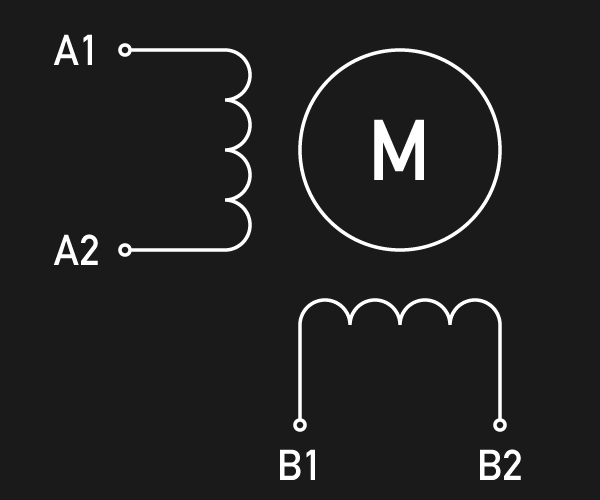
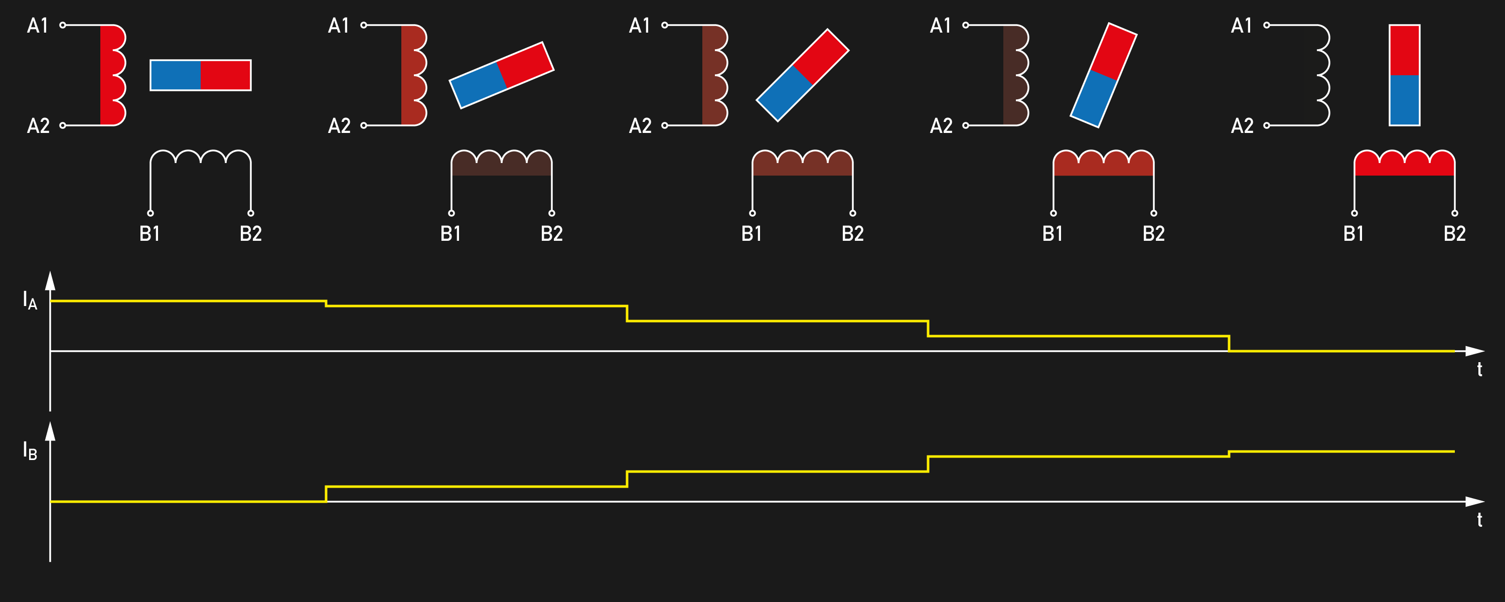
In a hybrid stepper motor, a microstepping-enabled motor driver will adjust the current in the stator coils to position the permanent magnet rotor in an intermediate position between two subsequent full-steps. A full-step is then divided into a number of microsteps, and each microstep is achieved by the two coil currents.
Many older industrial motor drivers feature only 4 microsteps (quarter-step mode), but today, 16, 32 and even 256 microsteps per full-step are commonly found. If we had a 200 steps per revolution stepper motor before, we now have a 51,200 steps per revolution miracle. In theory.
In practice, we’re still dealing with open-loop drivers, meaning that the motor driver does not know the exact angular position of the motor shaft, and it won’t correct deviations. Friction, the motor’s own detent torque and most strikingly, the external load that acts upon the rotor will go unnoticed by the driver. Without closing the loop through an encoder and a more sophisticated special driver, the best we can assume is that the motor will be somewhere ± 2 full-steps (yes, that bad) near its target position, which is the maximum deflection before the rotor snaps into the wrong full-step position, resulting in step-loss.
The incremental torque from one micro step to another is — governed by merciless trigonometry — only a fraction of the dynamic torque of the motor. To ensure that the motor shaft actually sets within +/- 1 microstep, we need to also reduce the load accordingly. Exceeding this smaller, incremental torque won’t result in step loss, but it will cause the same absolute positioning error of up to ± 2 full-steps. The table below shows the devastating relationship.
| Microsteps per full-step | Incremental holding torque per microstep |
|---|---|
| 1 | 100 % |
| 2 | 70.71 % |
| 4 | 38.27 % |
| 8 | 19.51 % |
| 16 | 9.80 % |
| 32 | 4.91 % |
| 64 | 2.45 % |
| 128 | 1.23 % |
| 256 | 0.61 % |
Source: Stepper Motor Technical Note: Microstepping Myths and Realities by Micromo
The good news is, that as long as we use a strong enough motor driver, and if we don’t exceed that incremental torque, be it through an external load or the motor’s internal inertia, the only theoretical limit for achieving microstep positioning accuracy are the motor’s internal friction and detent torque. These values depend heavily on the motor type, but are generally rather low (almost negligible) values. For example, the motor used in the following test is specified with a detent torque of 200 g cm. That’s merely 5% of it’s 4000 g cm holding torque. According to the above table, this motor should be capable of accurate positioning with a 16 microsteps per full-step driver.
So, does this theory apply? And do all microstep motor drivers deliver the same performance in terms of microstep positioning accuracy? I recently had the chance to test a few motor drivers for a project, and I was rather surprised by the results.
Test Setup
For the test setup, I borrowed the red laser pointer from my IR thermometer and attached it to the motor through a 3D printed fixture. A 3D printed mirror mount attaches a first surface mirror to the motor’s shaft and features two levers with a length of 100 mm each for loading the motor with a given mass. For the load test, I attached a mass of 100 g to one lever, which results in a load momentum of 1000 g cm through the lever. That’s a quarter of the holding torque of the motor used for this test: A Wantai 42BYGHW609 with 1.7 A per phase, 4000 g cm holding torque and 200 steps per revolution.


I mounted the motor assembly to a rigid windowsill and positioned it so the laser pointer dot is projected across the room onto a pocket rule attached to the opposite wall, about 6 meters away. The optical lever magnifies the steps for accurate readings. Initially, I planned to just note down the readings manually, but then quickly realized that writing a little Java image processing script to extract the readings from photographs could be done in a fraction of the time. So a DSLR camera was hooked up to my test electronics — an Arduino and a RAMPS 1.4 — to be triggered for acquiring the position readings. I certainly should’ve pointed the laser at the clean, white wall next to the ruler, but a simple threshold on the red-channel did a good job in accurately extracting the bright red laser spot from the ruler. From the reading on the ruler and the distance on the wall, I later calculated the angular position of the motor shaft.


All stepper motor drivers were tested in their 16 microstep per full-step mode. Before the measurement, the stepper motor was brought into a full-step detent position, and the mirror was aligned to a beam perpendicular to the wall. Then 16 microsteps were executed in one direction while triggering the camera after every step. After that, 16 microsteps were executed in the reverse direction, bringing the stepper motor back to its original position. Again, the camera was triggered after each step. Measuring the position in both directions should allow me to get an idea of the motor’s cushioned backlash (if present), but resulted in more interesting insights than expected. This test sequence was executed for every driver, both unloaded and loaded with 1000 g cm. The stronger drivers caused a bit of overshoot during the loaded tests, so they were given time to come to rest before a photograph was triggered.
It’s worth mentioning that all following results originate from the very same motor, and the same physical motor step to ensure comparability. Nothing has been averaged or otherwise processed, except from calculating the shaft position angle. However, all tests have been performed multiple times on different hardware (i.e. the same driver IC, but different breakout boards from different sources) to ensure sanity of the results. Even the quirky results (such as the DRV8825) were reproducible on different setups. Please be aware that the following graphs may give the false impression of a time-continous measurement. They actually show a series of discrete measurements at the marks on the x-axis, and the line graph only should make it easier to see the non-linearities at a glance.
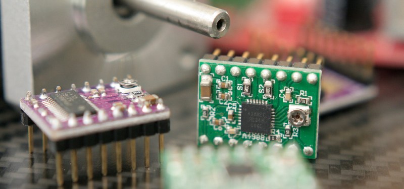
Allegro A4988
The Allegro A4988 on a Pololu-like stepper driver breakout board performed the best, both unloaded and under load. Even though it only delivers 1 A per phase, it achieved very linear, equally spaced microsteps in the unloaded test, with small but reproducible deviations from the ideal position within ± 1 microstep. Interestingly, the A4988 shows its largest deviation at the half-step position.
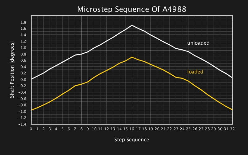
Unsurprisingly, the shaft position is deflected noticeably under load: more than a half full-step. There goes the dream of infinite resolution. However, the graph also shows that the full-step positions aren’t immune to this deflection, even though they are supported by the motor’s slight detent torque.
Texas Instruments DRV8825
The Texas Instruments DRV8825 on a Pololu-like stepper driver breakout board performed the worst. I repeated the measurement several times with different breakout boards from different sources, all of them resulted in curves almost identical to this one. However, since the driver is capable of supplying a higher current of 2.2 A to the motor, it shows a significantly smaller deflection under load at the full-step and half-step positions.
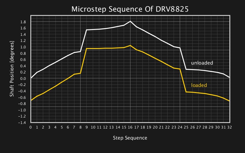
Both loaded and unloaded, the DRV8825 performs well until it reaches the half-step. Then, it leaps almost to the next full-step position within a single microstep. In the reverse direction, it again performs well until it reaches the half-step – this time in the other half of the full-step – before it breaks down to the original full-step position. The behavior is hard to explain. At least deficiencies in the motor’s current sensing path should affect the positioning more uniformly. I’m sure Hackaday readers can contribute to explaining, confirming, or disproving this behavior of the DRV8825, or maybe point out flaws in the measuring setup that could’ve caused these results.
Toshiba TB6560AHQ
I may admit I did not expect much from the cheap, red ST6560T4 driver board with four Toshiba TB6560AHQ 3A motor driver channels, but it’s a great driver IC and it did perform surprisingly well. The drivers were set to 2.25 A for this test and achieved a good linearity throughout the microstep sequence with a deviation of ± 2 microsteps when unloaded.
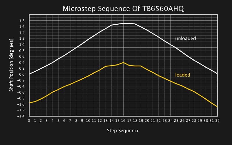
There were, however, reproducible non-linearities at the upper full-step position which the A4988 did not show, and the TB6560AHQ’s behavior under load differs noticeably from the idle behavior. Also, it’s surprising that the motor is deflected under the load by more than a half full-step, since the higher current should increase the motor torque similarly to the DRV8825.
Conclusion
I hope this write-up and measurement results help you with your design decisions and when working with these very common drivers. I did this tests for a rather narrow application, and they shouldn’t be generalized too much. Although I dare to conclude the following:
Stepper motors in heavier machines, such as CNC routers, that use open-loop microstepping, mostly benefit from the reduced vibrations and the lower torque ripple of microstep mode. They can not rely on microstepping as a means of increased positioning accuracy (at least not without keeping large torque margins), since a load may still deflect the axis’s position by more than a full-step.
However, small and light applications with low load and low friction may indeed resort to microstepping as a cheap trick to squeeze more accuracy out of a standard stepper motor. Even with a cheap, low-current motor driver, looking at the very well performing A4988, accurate angular positioning is possible, as long as the load is kept low, ideally within the incremental torque of a microstep.
As always, I’ll be glad to hear your thoughts, opinions, and experiences on the subject of this post. What’s going on with my DRV8825s? What stepper motor drivers do you rely on most of the time? Let us know in the comments!


Hello Everyone
I am using this kind of code to control a stepper motor, but it’s not working accurately:
dir(HIGH);
for(int p=0;p<20000;p++)
{
pulse(HIGH);
delay(t);
pulse(LOW);
delay(t)
}
For a fixed value of "t" the moving distance is same.On Increasing or decreasing "t" the moving distance changes with a different value for "t". As per my knowledge about stepper motor's, it should only affect the speed of a motor, not the accuracy.
I set my stepper driver to 6400 pulse/rev at maximum current .Any help appreciated to solve this problem
I love the wonderful explanation. Could you write up another article with the TMC2130 or TCM2208 for example? I am really curious how the silent modes of these compare.
I’m maybe not the first who have pointed this out, but wouldn’t it be possible to prevent load from deflecting the axis’ position by using an encoder like those found in servomotors, just a very very exact one, to get the angle of the shaft compare that with the desired angle to get the angle error, and combine that with a PID controller (or some more appropriate controller) to calculate an offset on the target angle to compensate for the load?
3 Years late to the party, but thank you for a top notch article! I don’t suppose you ever got around to testing the Trinamic drivers?
I’ve done measurements similar to the ones performed here on variety NEMA17 motor, driver, and drive current combinations. Even the MKS SERVO42B was examined. The purpose of my tests were to allow informed decisions wrt telescope mount drive design but I imagine the results might be useful across a wider range of stepper motor applications.
https://onstep.groups.io/g/main/wiki/Stepper-Motor-Accuracy
Can you try the experiment with DM542 microstep driver?
Technically I think the torque from your moment arm changes very very slightly as the arm rotates up and down. Ex. max torque when horizontal, no torque if completely vertical, so in the range of motion torque changes. Although this is definitely negligible and all the tests were subjected to the same conditions. Very helpful article. Thanks. More like this.
Nice job. Q: Are you taking into consideration the accuracy of the stepper motors themselves, which may or may not alter the results somewhat ?
I’ve been playing with the TMC2209 and an ATmega328P micro board but having some trouble communicatiing via the Uart(Usart). Pin configuration is available on the TMC2209 for up to 64 microsteps, but the higher 128 and 256 modes are only available via Uart configuration. Maybe I shouldn’t bother, after reading this.
Very late to the party, but,
U have chosen poor drivers, all!
microstepping accurately is a black art in itself!
U need a driver with hi quality software to issue accurate steps.. one that uses a DSP.
its a bit hard to explain in detail, a long story.
If U redo the test with a Good DSP based closed loop driver, the graph sh be perfectly linear, sh be.!
Clough42 does have a great video tuition on this, altho doesn’t graph linearity.