[Pabr] is trying to make dry ice the hard way by building a thermoelectric dry ice generator. The project is a well planned round trip through thermodynamics and cryogenics with a hard landing on the icy grounds of trial and error.
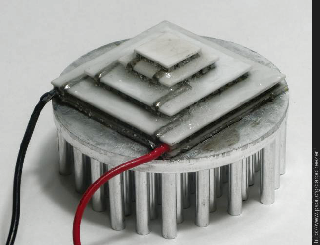
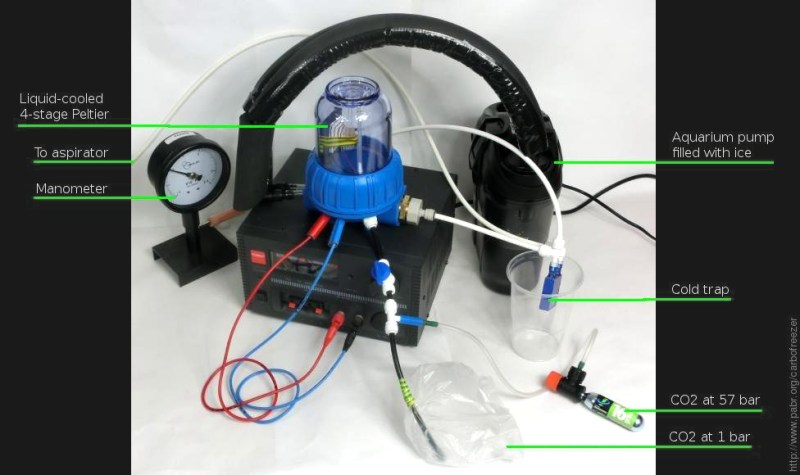
With sufficient cooling on the high-temperature side of the element, it should be well capable of achieving temperatures below -78.5 °C, the sublimation temperature of CO2. So far, [pabr] has built three different setups to expose small amounts of CO2 to the cold of the Peltier element, hoping to observe the formation of little dry ice flakes.
The first setup placed the Peltier element on a massive heatsink, which itself was placed in ice water. A chamber around the element was flooded with CO2 from a bicycle tire inflator. Dry ice was expected to form on the cold tip of the element, but unfortunately, nothing happened. The second attempt was to attach a liquid cooling system with a capable radiator and again, filled with ice water, to the high-temperature side of a Peltier element. A plausible attempt, but again, no success in dry ice production. The third setup moved the experiment to a quasi-vacuum chamber, where CO2 could be streamed onto the Peltier element through a fine needle. The low-pressure environment may have helped with the thermal insulation of the setup, but it also lowers the sublimation temperature of CO2 down to -100 °C. And once again, no CO2 snow formed.


This is not the end of this project, and [pabr] is still working his way toward thermoelectric dry ice production. One big challenge is the acquisition of capable measuring equipment. Thermocouples that are specified for cryogenic temperatures are expensive, and until now measurements have only been taken on the high-temperature side of the cooling element – relying on datasheet values to get an idea of what’s happening on the cold side. Do you have a good idea on how to make this work? [Pabr] will appreciate your suggestions, so let us know in the comments!


I don’t get it, if ample compressed CO2 is available, just whacking the valve wide open will have it spitting dry ice in seconds.
I’m pretty sure this isn’t exactly the mentality around here. He, and most people here, do stuff just because we can for the sake of exploring the pathway of building things, rather than just because of the need of a something.
RW has a point and if you had half a clue about the physics involved you’d have seen that rather than making the sort of observation a person with a liberal arts degree would make.
I thought the point of HAD is to share knowledge, even if it makes you feel stupid for not thinking of it yourself. Grow up.
I absolutely disagree with you. Matt is right – we ask not why, but how. If it’s dry ice you want, the best way to get some is to buy it from a store, but you don’t learn anything that way! In this case, making dry ice is just an excuse for exploring Peltier devices.
LOL stop behaving like an asshole and realize that people do thing for fun, to learn or just because it could be interesting… Hacking…
What I was half meaning, that as it is, due to depressurisation the CO2 should be pretty cold and minimal further heat extraction should see it solidifying… so even a badly insulated experiment at room temp that is marginally working as a heat pump should do it on gas delivered right to the cold end.
However, this looks ugly for heat paths and the amount of heat being supplied between the room at 20 and the cold end at a presumed -80 is enough to boil water, so think of the amount of insulation you’d want to put between a hot plate and a bowl of ice cubes to ensure they didn’t melt and that’s the kind of insulation it should be getting. Alternatively, get a 40 degree head start by doing it inside a freezer.
And if you pre-cool the compressed gas before it expands to just below the phase change point that is pretty much guaranteed. You could even use a solid state cooler to do it, strap the tank right onto it, and if that doesn’t get you there you make a double setup with the almost cold enough gas cooling the hot end of the next stage.
If ample compresses co2 avaliable… Have a Tesla turbine Generate the power.
What are the parameters for the Peltier devices in the stack? How much of their heat-pumping capacity is being spent just pumping out the heat that is generated in the Peltier device itself? The Tmax temperature difference is only obtained with 0W being pumped. At Qmax power, there is no temperature difference.
Digikey has RTDs for measuring temperatures down to -200°C for about $22. If you only need to go to -70°C then you can get an RTD for under $12 from them.
Exactly, the ‘hot’ side of a Peltier is the heat from the other side PLUS the heat dissipation that results from the power (Volts x Amps) used to power the Peltier so how could stacking them increase efficiency when the progressively increasing heat has to go through each stage to get to the heatsink?
Peltiers make extremely efficient heaters but are not good at cooling.
I think that’s why each stage is smaller than the last, you have more cooling power in each stage to make up for the increasing waste heat. I’ve actually seen this setup for sale on aliexpress before. Peltiers are terribly inefficient, but in this case they’re much easier and cheaper to play with than a cascading heat pump system.
Yes, but the hot side of one Peltier is only in contact with a small proportion of the cold side of another. The power of a Pelter is watts per square dimension so for this to work you would need to cover the cold side of the larger Peltier with copper and then insulate it from air if the temp is below air temp.
The way it is no makes no sense to me at all.
Yeah, I’d have wanted to build it with centimeter chunks of aluminum or copper between each stage, not really because you need more than a couple of mm for the heat spreader, but to give you some room for insulation to be effective in better isolating one stage from another with what I would best describe as sideflow heat leakage, the convection/conduction effects through air within a couple of cm either side.
@RW I really do like the idea of using a 1-2cm thick slab of Aluminium or Copper between each to allow an increased thickness of polystyrene insulation. But each metal block will also act like a thermal reservoir, and the bigger each is the longer it will take for them to cool down. You can never have a positive without some negative. With more insulation the efficiency is increased, but the lag time from initially turning the system on to steady state being achieved will be longer. Something along the lines of this ? https://i.imgur.com/GI8WmMp.png
The configuration seen is often used to cool electronics to a sub zero set point but only really for components that do not require large amounts of heat dissipation, It is possible for example to cool a camera or a photodiode (to improve it’s thermal noise levels) or a control the temperature of a laser diode (say to stop wavelength shift due to thermal effects, or to set the wavelength in the first place). Some thermal cameras also use this configuration to keep their pyrometers cold enough for use.
As you rightly say however the amount of cooling capacity falls off very fast as the stacks add up. I’ve no idea what the latent heat of freezing is for CO2 but you’d need to be able to pump that amount of heat through the peltier stack in order to cause the gas on the end to freeze, otherwise you’ll never have the final stack cold enough to be able to freeze the CO2.
Step one for me would be to get an accurate measurement of the cold temperature. A K-type thermocouple should work — it can be calibrated if you can source some LN2.
This guy has some good advice:
http://physics.stackexchange.com/a/81706
The first thing that I could do would be to measure the temperature of the cold side. Cheap thermocouples should work, but may need calibration. As gasstation says, you can also get an RTD for ~$22.
http://physics.stackexchange.com/a/81706
Solid CO2 won’t form at atmospheric pressure.
It’s liquid that won’t form at atmospheric pressure.
So dry ice doesn’t exist? Or am I missing something?
Yeah, dry ice doesn’t really exi…SH*T! YOU AIN’T SUPPOSED TO TALK ABOUT IT OPENLY!!! RUN. THEY’RE COMING FOR US.
I’m pretty sure any type K thermocouple can work at cryo conditions, you only need an amplifier circuit that can take the inversion of the voltage polarity that happens at around 0ºC. Or you could just have it only start measuring once it’s already bellow 0 and you shouldn’t have the issue with the polarity inversion.
A thermocouple will generate a negative volatage when the measuring tip is at a lower temperature then the other end (usually called cold junction or reference junction) of the thermoucouple wires. Thermocouples measures the difference temperature between the two ends of the wires. They do not measure the absolute temperature, like a thermistor would do. Assuming the other end is at room temperature (24ºC), then any temperature under 24ºC will generate a negative voltage.
Reducing the temperature of the liquid cooling portion with salt might be the easiest way to lower the temperature more (to -20°C or -40°C instead of 0°C). See
https://en.wikipedia.org/wiki/Cooling_bath#Water_and_ice_baths
Exactly, and you don’t really want ice, it is a good insulator, you want a very cold liquid that is a good conductor and you want to move it past the part to be cooled as fast as you can to maximise the thermal gradient at the interface.
He should be using 100% pure (or as close as he can get) ethanol or methanol in a sealed tub for his coolant (to reduce evaporation losses). If he runs it through enough cooling stages, with one stage below 0C that filters out any water ice that may form, that would help maintain purity. Alcohol will remain liquid well below the sublimation temp of CO2.
1. Definitely try to measure the temperature of the Peltier as then you’ll know pretty quickly if you’re achieving close to the temperature to freeze the CO2.
2. One method to try would be to evacuate the sealed vessel as much as possible and then fill with CO2 back up to atmospheric pressure, or above (you may need a better pump, like a diaphragm pump). You probably want to regulate the gas flow rate so it’s not too fast as flooding the chamber will probably prevent it from freezing. But CO2 will sink to the bottom of the chamber anyway, so mount the Peltier at the bottom of the vessel.
3. As has been said already, use an ice/salt bath which will be able to cool the vacuum trap to -20 degreesC.
CO2 is heavier than air so if you only want 1 atmosphere then just put the Peltier in a jar and slowly pour the CO2 in and it will sink below the air and lift push the air out from below.
They dont like ripple either. A few millivolts causes loss of efficiency.
this is good to know, thank you.
That’s the reason why PWM regulation of a peltier is a very bad idea.
Why not build a second Peltier Stack and work it in reverse as a sensor, so the temperature range creates a voltage that you can read with a voltmeter?
If it can create the temperature – then, as a sensor, it certainly can handle the same temperature swing.
Use a thermocouple of known accuracy to calibrate the Inverted Peltier Stack to determine if the temperature is linear, or not. Perfect job for an Arduino.
:
That would not work because the peltier element dissipates part of the energy in terms of heat. So it’s heating itself up. So the effect does not work when you mirror it to use as a sensor.
Also, it’s already known that the effect is not linear. It depends on the difference in temperature across the peltier element and also the amount of power you put into it.
As a sensor you would not need a stack. A single peltier would give you the voltage corresponding to the temperature differential. But the thermal mass and the thermal conductivity of such a peltier a s sensor would be very high. So you reduce the mass as far as possible: to a single junction. And then you call it a thermocouple. :-)
Of course this reduces the available output voltage, but electronic amplification is not that difficult.
I use Ktype termocuples to measure medical freezers at -80C with a MAX31855, which i then linearize externally and im accurate to about +/-3C…sometimes better.
Peltier devices haven’t show great efficiencies. I remember back in the day people using them to cool CPU’s, but you don’t see that much anymore.
yeah and most forum threads dealing with peltiers ended with “i killed my computer” either condensation killed their boards or the peltier died insulating the CPU and frying it instantly but efficiency was never a big issue in this application…
I’m not seeing any insulation, I’d have Styrofoam around everything that I wanted to keep cold.
I agree
Put pieces of aluminum, ideally an alloy optimized for heat sinks, between the Peltiers so that the heat from the hot sid eof each is spread across the cold side of the next, larger one.
Insulate! The edges of a Peltier need to be insulated so condensation won’t get into it. That can damage the element. You want only the cold surface exposed to the CO2 and the hot side shielded so no warmed air can make it around to what you want to chill.
Are there Peltiers optimized for generating power from a temperature differential instead of moving heat with applied power? Thinking of building a waste heat to electricity converter for the exhaust pipe on my 1 ton truck. Lots of room under it for a large device and for airflow to cool the outside.
Since it’s a flatbed there’s room to put on a chimney for convection cooling air to rise up from under the cab to under the bed. Have to have something like that for stop and go traffic. Putting a fan on it would somewhat defeat the purpose of getting “free” power to offset some load on the alternator.
These are indeed thermo electric generators. Many are able to be used at high temperatures (200-350 degrees C across both faces) but the power generated is fairy pitiful for the price you spend. (3W for a 30 x 30mm module @£25). I’m sure you could get them cheaper.
I believe you can get these as kits for this purpose and also they don’t actually help. The theory is that that’s wasted heat but if you take heat out of the exhaust gasses they become a little more viscous and provide more mechanical resistance for the engine. Given the poor efficiency of peltiers that extra mechanical load offsets the power generated.
If however you wanted to add a peltier to say the hot hose going to the radiator, that should be almost free power.
My knowledge about chemistry is a bit poor, but I wonder, if you are cooling it that far, and you have many contaminants (as I bet there is not only CO2 in the chamber), wont they affect the freeze point? And further, will the CO2 first become liquid, so it will flow away. I also wonder how much CO2 you need for a piece of dry ice, will it even be observable?
Good luck getting it working :)
For carbon dioxide to become a liquid you would require at least 5.1 standard atmospheres (75.5 PSI).
Dry ice expands roughly 80x, each CO2 cartridge has 12g (approx 6L), there are also 40g cartridges for some bike inflators. So there’s more than enough to get detectable dry ice.
Not enough to do anything, but enough to play around a bit.
It’s probably better if the cold side is within a chamber, so that ‘fresh’ new air doesn’t circulate to keep warming up the cold side. Now it’s like keeping the door of the fridge open.
oops forget what I said, that’s what he did. dOH!
1) Aerogel as an insulator will maximise efficiency and it can be purchased in small quantities quite cost effectively.
2) Use something other than water for the liquid cooling, perhaps a Glycol based coolant, but you’ll want a sealed system and you might need to worry about corrosion of the heatsink.
3) low temperature silicon potting to protect the peltier elements, or even perhaps a synthetic grease?
4) I don’t know how important the pressure of the CO2 is but you could also make your own CO2 using baking soda + vinegar or yeast + sugar? Save you the cost of the CO2 canisters eventually, especially as yeast is pretty low maintenance.
For applications that do not require the insulation to work up to 1,473 K (1,200 °C; 2,192 °F), Polystyrene is a lot lot cheaper and so close in performance, I would use it.
Aerogel – thermal conductivity: from 0.03 W/m·K
Polystyrene – thermal conductivity: from 0.032 to 0.038 W/(m·K)
Thanks for all the feedback ! To address some of the concerns that have been expressed:
– Peltier module selection: I think I understand how these things are spec’ed. Now the question is whether the performance ratings are realistic. I’m already cooling the hot side 22 K below what should work. I can go lower, but antifreeze in the kitchen freezer is a no-go. Also, I have no data on how DTmax degrades at low temperatures.
– Measurements: I wasn’t familiar with lab thermometers with interchangeable probes, so thanks for the advice. Will try that soon.
– Insulation: The pump and coolant lines are wrapped in foam during operation. The Peltier module is now in near vacuum (50 mbar) but I haven’t really estimated conduction leakage, and water vapour from the aspirator is definitely a concern. I haven’t done anything about thermal radiation yet.
– Potting: Manufacturers recommend epoxy rather than silicone. I believe it’s even better to work in a vacuum.
– Ripple: I’m using a 9kg 25A linear PSU rated 3mVpp. These things are designed for amateur radio where switch-mode power supplies are not welcome.
– Use of CO2 cartridges: This is for convenience. Ultimately I should be able to freeze CO2 from dried ambient air. Using water ice from the kitchen freezer is cheating too. The spirit of the project is to make dry ice without any mechanical compression.
I would suggest to use 4 independent power supplies, so you can adjust each element to their optimal characteristics (data sheet curves), also add heat spreaders between the modules and polystyrene isolator.
Like this: https://i.imgur.com/RaPeaCW.png
The copper plates are to distribute the thermal energy over a larger area, which should increase the efficiency of the cooling.
For initial testing I would start with a tiny volume of CO2, surrounded by a lot of insulation. The smaller the volume you have the less time you need to extract energy for it to change state.
Right now I am using a prefabricated multi-stage Peltier module. There is a single ceramic plate between the stages, which means it is manufactured as a multi-stage device rather than assembled from single-stage modules. And there is a single power supply for the four stages.
I thought it was a good idea to use a (presumably) optimized design and avoid reinventing the wheel, but now that I look into the thickness and thermal conductivity of the ceramic plates, maybe I should do the dimensioning myself.
There may be advantages to using 6 standard sized TEC’s ( removing the heat from 1 into 2, and removing the heat from 2 into 3, and then water cooling the external 3. If you are pumping 60 watts into each TEC that would 360 watts which is going to boil water fast. Or maybe 5 – 1 into 4). The thickness of all TEC’s are small to keep the internal I^2 x R losses as low, as possible.
https://hackaday.com/2016/09/19/thermoelectric-dry-ice-generator-does-not-work-yet/#comment-3207567
I see your two main problem being able to dissipate all the heat generated internally by the TEC’s, and second having enough insulation to keep good thermal separation between each TEC’s layer of ever decreasing areas. Also good thermal insulation around the target CO2 gas. Maybe use a thermos vacuum flask for the CO2, and a cold metal finger from the cold side of the heat pump surrounded by Styrofoam.
I wish there was an edit button. (with the tip of the finger exposed near the bottom of the Thermos flask).
The Thermos/Dewar with cold finger is on my to-do list ( http://www.pabr.org/carbofreezer/carbofreezer.en.html#future ) but the best specs I can find, for long-term cryogenic storage, is 0.08 L of liquid N2 evaporation per day. This translates into 0.1 W of leakage at -80°C. I’m not sure yet whether the Peltier module can even compensate that.
Also, a cold finger is known to work for liquefying N2, but dry ice might form an insulating sheath around it, requiring mechanical scrapping.
Perhaps the low pressure environment is allowing the water on the walls to boil at lower pressure like in a heat pipe.
I think only one other person brought this up, but CO2’s enthalpy of sublimation is 571 kJ/kg. So if you want to convert, say 1 gram of CO2, you will need 571 Joules, or 571 Watt-seconds of energy. So not only do you need to cool it to -78.5C, you then have to pump out 571 Joules per gram.
Considering that peltiers are really poor at pumping at their max temperature differential, you may find that you only have the ability to move say, 1 W of power from the area of your smallest peltier. In this case, it would take you 571 seconds to see only 1 gram of dry ice. That’s hardly instantaneous.
I would do the math on the peltier pile again… measure the voltage and current draw of each and use the data sheets to figure out how much power it is using. Make sure you can pump that power through at the temperature differential you are looking for, then make sure that you have enough headroom at the target temperature to pump out the necessary energy. Then give it enough time, and shield it from radient heat and other sources that may melt the CO2 as it forms…
If you want a food safe antifreeze (kitchen freezer) then use vodka. :-) Or any other ethanol/water mixture. The linear PSU seems overkill, the ripple need not to be that low.
But I am not sure if the idea to freeze the CO2 out of the air is possible. You need to cool very much air down to the freezing point of the CO2, which constitutes only about 0,03% of the air.
Re: only 0,03% CO2 in air.
Yes, that would require a huge counterflow heat exchanger. Or maybe let ambient CO2 diffuse down though a column of air and onto the cold plate. Conduction loss would be negligible if the air remains undisturbed.
On second thoughts (and some googling), the sublimation temperature depends on the *partial* pressure of CO2, so I would need to cool down to -150°C instead of -80°C. Or increase concentration with something like zeolite.
Not only that, but you still have to pump out 571 J/g at that temperature. If you can only pump 1W and you fill a container with a 9g CO2 cartridge (and assuming the CO2 displaced everything else, and that the thermal resistance of the container kept heat conduction into the chamber to less than 1 W – highly unlikely) you would still have to wait 9*571 seconds before you saw significant dry ice form. like boiling water in a pot, you have to bring the temperature of all of the CO2 down to -150, then take out 571 Watt-seconds/g on top of that.
you might want to look at putting your chamber inside a glass vacuum insulated chamber…
Can you use propylene glycol as antifreeze in the freezer? It’s a lot less toxic than ethylene glycol. It’s even in frozen daiquiri mix. You can drink it when you’re done.
I like the idea (of course) but he really can’t expect to collect dry ice from the atmosphere given the small amount available. Maybe this approach would be better suited for a liquid nitrogen collector; I’m not sure if peltiers can get to -200C but assuming it was possible, it would probably meet with more success. Unfortunately, he is most likely going to make a very expensive ice machine. To have this feasibly work, you will need to really really dry out the air to prevent moisture from contacting the low temperature element. Consider a multi-stage system with pre-coolers (like a dehumidifier) and dessicants prior to exposing the air to the freezing part. Good luck! I hope you learn something about TECs.
A few notes. Vacuum is bad. You are making more work for yourself. Power supply could be run into a tec controller. Over build by more than 20%. Closer to max tecs drop in efficiency. Use windshield fluid(winter stuff) as replacement for antifreeze. Just some thoughts
If he added sufficient salt to his ice bath, he could lower the temp of the bath to -20*C (IIRC) and about -40*C if he use CaCl2. That might help significantly with the temp differential…
Very cool experiment, I had thought 3 was the limit of effectiveness of stacked peltiers. (Maybe do a double check at the temperature rreduction after each stage to be sure the last one is helping). Anyhow a sterling cooler would have been my recomendation for a DIY cryo setup.
http://fpsc.twinbird.jp/legacy/en/sc_td08_unt_e.html
https://www.ohio.edu/mechanical/stirling/engines/beta.html
+1 A modern sterling engine would be far more efficient (40-60% vs 10-15% for Peltier).
https://www.youtube.com/watch?v=GqIapDKtvzc
https://www.youtube.com/watch?v=GFfMruoRMGo
I know, I know… The SC-TD08 free piston Stirling cryocooler can pump 25W at -80°C. But it is listed at $680 and I don’t know how to buy it.
For half that price I can order between 1W and 20W of Peltier cooling power oinline, shipping the next day. The efficiency will be terrible (much worse than 10%, actually) but if the purpose is to make a few grams of dry ice for entertainment purposes once in a while, I think it’s worth trying to make it work, as an alternative to the CO2 fire extinguisher trick.
On the bright side research into space cooling has shown that Peltier coolers can typically get down to 170K, so -80C is not impossible.
http://www.eng.ox.ac.uk/cryogenics/research/cryocoolers-for-space-applications
I was wondering if there might be some physical change inside a Peltier device that would prevent it from reaching -80C.
Another option might be to use a device like the TEC1-12730 (~16 Volt ~30 Amp), 6 of those should do the job but would use about 1500 Watts of power and would require a fantastic cooling system. Think in terms of the energy used by one and a half kettles boiling water, getting rid of that much energy fast.
-90C can be achieved in camera sensor cooling with 5 stage tec.
Use a heatpipe for cooling the hot side. It is much more efficient than copper. Can ve bought in pc parts shop.
Another way to go is to use a cold copper head cooled down to -40 using a mechanical fridge. It was marketed as Vapochill and used for pc processor cooling by overclocking fans
A bucket or ice, an aluminium heat sink and a single 6 amp TEC1-12706 can get you down to -50C, so 6 (or possibly 3 if ICE is involved) should if configured right be able to get you down to -80C
https://www.youtube.com/watch?v=qYvsDBf72gA
That video was encouraging, thanks. The block of ice could be well below 0°C initially, so I’m not sure about the 50K. Anyway I can easily get 42K out of a $2 TEC1-12706 (that’s 62% of the rated Dtmax) whereas my expensive four-stage module does only 48K in open air (43% of DTmax) and 60K with vacuum insulation (54% of DTmax).
I actually ran a quick test myself using a block of ice and a 30 mm x 50 mm right angle piece of aluminium frozen into about 200 milliliters of ice, removed from the freezer at -8C. I placed a 40mmx40mm TEC1-12706 partially sitting on top held in very poor thermal contact by gravity and 10 mm of the hot side was sitting in air! But I was able to get the cold side down to -42.4°C before the ice started to melt and the temperature started to shoot up.
I can totally see a much larger heat sink with a large surface area in direct contact with far more ice getting down to -50°C exactly like they did in the above video.
I would experiment more, but I don’t have anything that will measure below -50°C and I only own one TEC1-12706 (at the moment). Still I might try a very large aluminium heat sink with a much larger surface area and freeze it suspended in the water. I would add salt to the ice to drop the starting temperature down to -21.1°C ( http://antoine.frostburg.edu/chem/senese/101/solutions/faq/zero-fahrenheit.shtml) , but it would then probably be below my ability to measure the temperature (currently).
Ultimately I do not think that using ice (with or without salt) would be the ideal solution, but it might help to get some useful calibration data for the peltier coolers, the only curves I’ve seen have the hot side at a constant at 25°C, 30°C, 50°C or 70°C.
Ice is not a great conductor, you can probably get an immersion heater and shove it in a coffee can lump of ice, and have a pocket of boiling water in the middle before it melts it’s way out the sides.
I fully agree, but I’m not using the conduction. I’m using the energy required for the ice to change state from a solid into a liquid. 334 J/g. and to get the maximum benefit from this I need a massive surface area interface between the heatskin and the water, the more surface area the better.
sorry, “ice” not “water”, I really wish HAD added an edit button.
Think several things going on here, not only lack of cooling energy I think too much stacking potentially, too late in evening for me and maths but ….. but surely there will be an in air energy feed back to the previous cooling stages being un-insulated as the petlier underneath the one on top is going to have surface area warmer than that being attempted by the one above. so the air inside would be largely dominated by the largest petliers surface area being presented outside the bounds of the next stage. Ideally you would thermally isolate the 3 lower petliers maybe with aerogel so no surface area losses and each stage gains fullish potential of the stage below.
For those still interested: While reading up on lab vacuum techniques 101 I learned that the thermal conductivity of gases does not depend on pressure at macroscopic scales. Benefits start at 0.1 mbar, way below what a water aspirator can do. Cheap rotary-vane vacuum pump on the way…
This is VERY interesting!!!.. I have played around with TECs for a while, and they are fun little buggers. C02 needs a helping hand to remove heat so I would continue to explore the use of antifreeze in combination with C02. If you insists on using the small 12g cartages (best to grab a 20oz paint ball tank instead though), then make sure they are inverted so that any of the liquid C02 contained in them would be bottom and the gas c02 component would push the liquid out first (its the liquid C02 that would create the snow, not the gas part)
Bumo, Just discovered this because I was playing with the idea of a Dry Ice Truck, Covid Vaccine is making Dry Ice ultra expensive, so a dry ice manufacturing facility on wheels might be a good investment, Espcially if it can owered with solar on the roof.
Probably needs more peltier elements. They are only 50% efficient max ( e.g. it takes 100 joules to move 50 joules ) and that number gets rapidly worse the higher the temperature difference. More elements = less difference between elements.