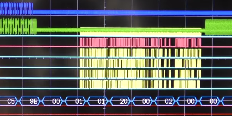
[Mike] wanted to drive several SPI peripheral from a PIC32. He shows how much latency his conventional interrupt handlers were taking away from his main task. He needed something more efficient. So he created the SPI channels using DMA. He also made a video (see below) with a very clear explanation about why he did it and shows oscilloscope traces about how it all works.
Although the project is specific to the PIC32, the discussion about DMA applies to any computer with direct memory access. The only thing missing is the code. However, there are plenty of examples on the web you can look at, including a Microchip webinar.
DMA is a powerful technique, although it can be tricky to debug. Big computers have used it for ages for high performance I/O, like disk drives or displays. We’ve covered DMA for the ARM before. Not surprisingly around here, driving LEDs seems to be a common use case for DMA.


I have to confess, even after watching this I would still probably do it with external glue logic or a bigger micro
Interesting – why do you think you would choose to do it that way? To me, this seems elegant in that it uses minimal hardware and is not particularly challenging to pull off.
Well for one im not a very talented firmware guy but adapting this across micros would be a challenge (and i can find myself changing micros up to 5 times during dev of a product) and the amount of debugging and timing constraints i would prefer just to dump via DMA and use AND gates to toggle between lanes
I am excied tesf it on my new board https://hackaday.io/project/14792-pixi32-chipkit-compatible-slim-pic32-usb-stick
Very handy!
I wish he would keep his quick nervous hands out of the picture though, very distracting.
I think you missed the pun in your first sentence (based on the second one)
For source code on PIC32MX using DMA check my VPC-32 project on github. It use an SPI channel to output video pixel.
https://github.com/Picatout/vpc-32
The relevant file is hardware/tvout/ntsc.c
You can generate video with that!
Yes an SPI can be used to serialise pixels of b&w video. The DMA channel is quite usefull here because the interrupt can leave as soon as the DMA is configured, freeing CPU for other tasks.
In fact, on the pic32mz series I’ve even done color SVGA (800x600x8bpp) with a 40MHz pixel clock using the DMA to GPIO. The nature of the DMA state machine on the PIC32 means that of you just set up a transfer and let it rip you will transfer one cell every 5 sysclk periods (40MHz for a 200MHz sysclk, or 25MHz for a 125MHz sysclk). To do this you have to run the I/O port a bit out of spec by setting it’s PBCLK to sysclk so there are never waitstates writing to the GPIO but the overall toggle rate is not out of spec and for a hack it’s alright. I believe on PIC32MZ*EF series chips your peripheral clock divider can be 5 at which point you no longer need to over clock the GPIO.
So, yeah, if you wanted to sample the IO pins every 33ns for instance, set your peripheral bus clock the GPIOs hang off to 30MHz and your sysclk to 150MHz and you’re good to go.
You can then either set the bus initiator priority so the CPU waits for the DMA –or– you can use the fact that your on-chip SRAM is divided into two independent 256KB banks and keep the CPU in the other Bank when sampling.
Additionally, since you can have more than one DMA work off the same trigger you can record the value of a 32 bit timer as well as start sampling when the trigger fires…
Coming a bit late into discussion, sorry… Thank you to both of you for sharing your experience here, and it is nice to have a chance to look at your code, Jacques.
(Lars, did you publish some stuff related to your color SVGA project ? After these informative insights, I would be interested to get a closer look at your implementation.)
DMA is the workhorse in many embedded systems where data needs to be pushed around without any modification. Older microcontroller usually either have a single or double-buffered register for SPI, UART, etc. Some have longer FIFO buffers, but most just have highly flexible DMA controllers, complete with priority scheduling.
I just love watching DMA controllers pump huge piles of data like they’ve never done anything else.
It’s a shame that microchip cripples their own GCC-based PIC32/PIC24/dsPic33 toolchains for profit. The hardware seems quite impressive.