A few weeks back, we got a taste for two-stage tentacle mechanisms. It’s a look at how to make a seemily complicated mechanism a lot less mysterious. This week, we’ll take a close look at one (of many) methods for puppeteering these beasts by hand. Best of all, it’s a method you can assemble at home!
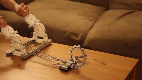
Without a control scheme, our homebrew tentacle can only “squirm around” about as much as an overcooked noodle. It’s pretty useless without some sort of control mechanism to keep all the cables in check at proper tension. Since the tentacle’s motion is driven by nothing more than four cable pairs, it’s not too difficult to start imagining a few hobby servos and pulleys doing the job. To get us started, though, I’ve opted for hand controllers just like the puppeteers of the film industry.
Enter Manual Control
Hand controllers? Of all the possibilities offered by electronics, why select such an electronics-devoid caveman approach? Fear not. Hand controllers offer us a unique set of opportunities that aren’t easy to achieve with most alternatives.
First, these controllers offer a purely mechanical solution. What that means is that they’re relatively simple in terms of parts. There’s no power supply to worry about, no code bugs to scratch our head over. Once we fasten our cables in all the right spots (and unkink the snags), the controllers just work.
Second, unlike a hobby-servo alternative, these controllers are dead silent when driven by our arms. That “chirp” that’s so characteristic of those cheap hobby servos just isn’t there; and, unless you’ve got some crunch to your wrist and elbow movements, these hand controllers keep the sound of the tentacle motion down to a minimum. For aspiring filmmakers, a quiet prop might sound more appealing than a whiny electronic alternative — even if they can mix-or-delete that sound away in post-production.
Third, unless we have a nice haptics controller, hand control gives us one additional piece of information: force feedback. Can’t squirm any farther into the table or through an obstacle? An electronic solution without a force sensor wont know when to stop tugging. Since our hands clasp the controllers that clamp the cables that carry the tension force through the length of the tentacle, we’re in direct contact with the forces experienced by the tentacle. Because we can feel this force, we can feel the “hard-stop” when our tentacle hits a dead end in its range of motion.
Finally, professionals still use hand controllers as one of many options in their repertoire for puppet controllers. While we’re not machining our controllers from 6061 aluminum like the pros, our plastic alternative isn’t far from tested-and-tried schemes of the past.
Backdrivability
I mentioned above that force-feedback comes from the controller’s “hard-wired” relationship to the cables in the actual tentacle. To make this point a bit clearer, one of the oddball consequences of this construction is backdrivability. What this means is that, with our hands, we can manipulate the tentacle, and those movements will feed back up the cables to then drive the controller. This nifty feature is an unavoidable consequence of how the cable is wired. What’s more, it’s an important reminder that the forces that this tentacle “feels” will be carried up through the length of the cable back into the controllers. In other words, if we’re controlling our tentacle by hand and someone seizes it to prevent it from moving, we’ll feel that force carried into the controller to tell us to stop forcing more torque into the controllers.
Controller Inspiration
This controller is targeted for fab on a laser cutter. (Ok, Ok, there’s one 3D-printed part in the BOM too.) The design, though, is just an adaptation of controllers that I’ve seen from special-effects controllers online.


Most controllers that I’ve seen so far tend to separate each degree of freedom into two separate axes, rather than integrate them both into a single multi-axis gimbal. I’m guessing that the reason behind this is ease of fabrication, but I also think that separating each degree of freedom into it’s own pivot point also makes the tentacle far easier to puppeteer with broad, deliberate, hand gestures that require distinct arm movements.


I’ve modeled my controller to take after Landon’s from the Stan Winston Tutorial series. That said, since I was aiming for fabrication on a laser cutter, the finished controller took on an appearance that’s similar in character but separate in both look and feel.
I picked a laser cutter for part fabrication since most of us don’t have the luxury of easy access to a nearby CNV milling machine. Laser cutters, on the other hand, are a lot more likely to pop up in schools and hackerspaces — not to mention that Pololu and Ponoko will also kindly laser cut your parts and ship you back the results.
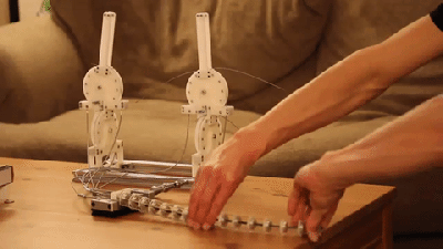
As for the actual design, my biggest change comes from swapping pulley orientations. Moving the pulley that controls the tentacle “pitch” down to the lower section forces the user to use their entire arm to control that “up-down” motion. In contrast, getting that same “up-down” motion from Landon’s controller relies far more strongly on just wrist movement. That orientation change on these controllers puts far less strain on my wrists, and I hope others can reap the benefit of that swap.
Controller Nuts and Bolts
Just like the tentacle, the controller is also a whirlwind of new parts, most of which we haven’t covered before until now. Here’s a quick breakdown of the key features and components that make this mechanism work.
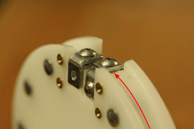
Keystone Angle Brackets 612 and 621
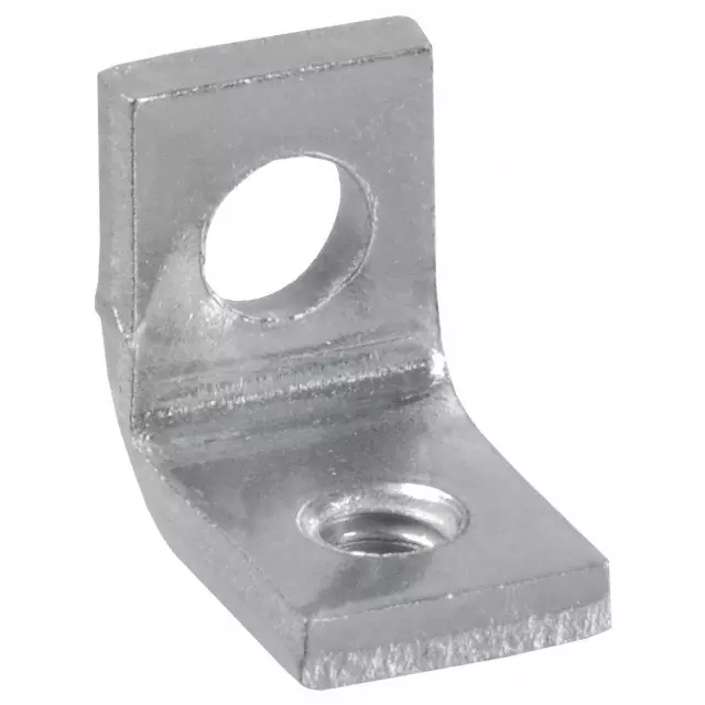 Few off-the-shelf hardware parts have been quite as enabling as these two angle brackets, formally known on Digikey as: 612K-ND and 621K-ND. I have so much affection for these parts because, to date, I can’t seem to find any other commodity angle bracket that’s quite as tiny as these two culprits. Furthermore, depending on the bracket type, one or both holes are tapped with a 4-40 thread feature, which makes them ideal for fastening into tight spots without having to worry about accommodating space for an additional screw.
Sure, nothing’s perfect, and these brackets are no exception. However these brackets are being fabricated, they seem to be popping off the assembly line and into my livingroom at an angle that’s not perpendicular enough to use them for any sort of precision alignment. That’s no dealbreaker, though. I use them here to fasten the two pulleys perpendicular to each other on the controller. In this case, the actual plates of Delrin do the work of holding the two pieces in the proper configuration relative to each other. The angle brackets just fasten them in place.
Laser-Cut Rivet Pulleys:
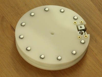 In a bold step to truly push Delrin as a functional material for rapid prototyping, behold my best example of a functional part so far: laser-cut pulleys! These pulleys are a four-plate concoction. When riveted together (since Acetal doesn’t seem to care much for glue), they behave like a single unit.
To the untrained eye, it looks like an off-the-shelf part. However, two necessary features make this custom design easier to build up from the plates rather than adapt from any off-the-shelf counterpart. First, each pulley is doing the actual heavy lifting of simultaneously loosening and slackening the cable pair that creates the actual movement. To do so, those cables must be rigidly fixed to the pulley at a single point. For that job I’ve embedded two cable clamps into the top of the pulley. Next, this pulley needs to screw down into either a handle, if it’s used on top, or a second pulley, if it’s used on the bottom.
In both cases, those connection points are offset from the center, and most off-the-shelf pulleys simply don’t have any offset mounting holes or attachment points. With some light CAD work, I embedded mounting holes directly into the plate. The result is a pulley with mating features already located where they need to be once the parts are laser cut. What’s more, since the hole pattern that drives these mounting holes is the same for the handle and the joint connector, both top and bottom pulleys are identical — a nifty feature if I ever find myself mass-producing these controllers. (Unlikely, but good habits make scaling easier when it does count!) For the custom needs surrounding this pulley’s end-use, a custom revision just made sense, and they hold up just as nicely as any off-the-shelf solution.
Rivets
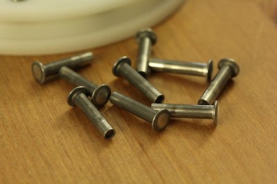 The pulleys might start off as four plates, but once I assemble them together, I can forget about ever needing to take it apart. My pulley will forevermore be a pulley, not the parts that constructed it. Since taking it apart doesn’t matter, I opted for rivets. Rivets give the pulley a polished look, not to mention that assembling these pulleys gives us the chance to enjoy a satisfying squish as we squash each rivet into place. On a more practical note, inserting each rivet is much faster than threading a hole and screwing in a screw for each hole.
DIY Cable Clamps:
 In the homebrew rapid-prototyping world, we’re usually limited to soft or brittle materials since most of our parts are coming off of the 3D printer or laser cutter. What’s more, Delrin has yet another problem: it’s notoriously slippery, so our wire clamping feature can’t rely on pressing the wire against a Delrin plate. The wire will just slip! In these situations, we can redirect critical stress-bearing features to off-the-shelf hardware. Here, our cable clamps are made from two steel angle brackets. The wire rope simply slides through the cavity between these two brackets where it can be screwed down between a steel-on-steel connection.
Cable Conduit Termination with Ferrules and 3D Printing
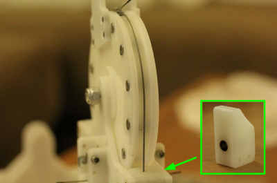
Each of our cable conduits must terminate at a fixed point on the controller such that the wire rope can extend beyond the conduit and clamp into the pulley. That way, when the pulley tensions the wire, the conduit housing doesn’t move with it. Instead, tugging the controller merely changes the wire length from the pulley clamp to the end of the conduit.
For this part, I opted for a 3D-printed block with a ferrule pushed into it. These metal ferrules are pretty standard components from bicycle and motorbike shops, and it saves the 3D-printed part from wearing out over time. Just like the cable clamps made from angle brackets, these metal ferrules take the stress off our custom parts and redirect them to a sturdier part that we can find off-the shelf. Here, our cable conduit puts more stress on the ferrule than the pocket of the 3D printed part.
Extrusion Attachment Points
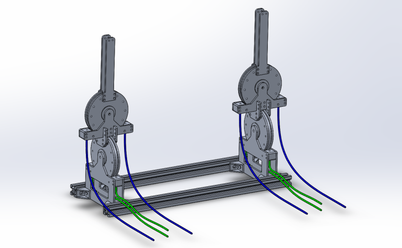
Since I can’t predict everyone’s shoulder widths, I added a few attachment points for Makerslide angle-brackets. The benefit here is that anyone can cut down an extrusion length and space out these controllers in a way that’s comfortable for them.
Get Ready for the Assembly Round:
For the curious, I’ve been doing my best to keep an up-to-date photo log and CAD model of this adventure. Tune in next week for a fully-blown BOM and dxf suite to recreate these controllers and the tentacle at home.


Looks pretty nice. Could one add a vibrator to the end? Would no longer be purely mechanical but it might improve the end usage in some cases. Asking for a friend.
You would need to add the wire inside the tentacle and place the vibration motor at the tip, or if you wanted , you could use a flexible shaft like those found on multi-tools and have the motor on the stationary portion.
I’m also assuming you’re wanting to skin this, so I suggest you find a food-grade silicone or at the very least, a platinum-cure one. Most normally available silicone releases acetic acid as it cures which can cause irritation.
Personally, I long for the simpler times, like 8 am this morning, where the creepiest thing I knew about was Furries. :-P
Legitimately jealous that the creepiest thing you can think off the top of your head is “furries”
They’re a “soft” target, badoom tish.
*swipes at with paw*
Says, the phurry-phobe. I can think of dozens of things much scarier like the personal hygiene of the people at fast food restaurants, tornadoes in the summer, spandex on not-thin people, the +20 trillion $ US national debt, the fact that we WILL some day run out of oil, nuclear proliferation, population density reaching a critical point allowing for epidemics, autonomous robots with enough strength to crush you and mobility, ….. Now that stuff is scarry. People running around in costumes usually aren’t dangerous although I’d avoid weird looking clowns lately which is sad considering I have friends who are graduates of clown school and love entertaining children, especially those who are sick in the hospitals.
“I have friends who are graduates of clown school”
I’ll thank you not to refer to Princeton that way.
furry here, i’m using a similar design to make myself a tail so uh sucks to be you i guess
bathroom silicone indeed releases acetic acid, but not so much that it will (keep) causing irritation: it just washes away. The other class of silicone (which unlike bathroom caulk is not a mess to prepare) is tin-curing silicone. Tin is a metal you’d better not ingest, but also not very hazardous in silicone. There probably are dirtier things where this ‘friend’ is aiming his tentacles I guess.
But of course, it makes you look good to point out futile security/health risks.
Personally, I would go with a food grade RTV 2 part platinum silicone.
Are you making a cast, for a friend, with the silicone? Then the acetic acid will indeed cause irritation.
Food grade RTV 2 part platinum silicone does not contain any acetic acid. Acetic acid is a 1 part cure silicone.
I’ve read that the tin cured stuff degrades; anyone know a realistic time frame?
Tin is used in toothpaste, I would hope it’s not too toxic.
Not in any toothpaste I use. Tin is used in a fluoride compount to strenghten tooth enamel, but it has a side effect of discoloring the teeth and people have allergic reactions to it, and if you swallow it it causes indigestion, so they rather use sodium monofluorophosphate or sodium fluoride instead.
I think backdriving it would make for a fairly efficient way to program the course grain movements of a complex or lengthy set of moves, whilst still retaining a fairly fluid/organic look.
This seems like a good opportunity to use Voice Coil Actuators. VCAs are excellent at short, precise movements and can take advantage of the feedback the cables would provide. Very cool and just short of extremely awesome.
I doubt they’re strong enough for this purpose.
Just need stronger coils!
Add a torque amplifier capstan to the voice coil.
Voice coils would struggle to overcome just the friction in the cables… Good old CNC servos (not the dinky RC ones) would be the way to go, the DC ones aren’t that expensive.
Put a camera on the end and this could have applications from search and rescue to colonoscopy, not to mention it could be a huge advance in tentacle porn!
Already been done. The Svakom Gaga Intimate Sex Selfie Stick HD Camera Vibrator is a dildo equipped with a high-quality camera and LED lights (it’s probably dark in there). $180 or so, retail.
What an age we live in!
Just nit picking, but it seems that one clamp would suffice if the cable / rope is long enough and it threads up through the tentacle, loops around the ‘pulley’, then back through the tentacle… maybe placing ferrules on each side of the clamp if you’re worried the clamp may not tighten up enough. Or, maybe just run the cable, the same way, looping around the clamp’s screw, maybe tying a knot.
With a single clamp how do you tension the cable?
“With a single clamp how do you tension the cable?”
Maybe like it’s done with two clamps, two cables and ferrules on the cable by the clamp?
I mean, maybe by pulling taught on the cable and applying a ferrule on the end by the tentacle?
I’m not sure how it’s done, now, so I can only make assumptions.
Presumably, there would be some adjustment in the cable guide to take up extraneous cable/rope slack, since they will stretch and contract with humidity if they are rope and not cable. Basically, just like how bicycle cantilever brakes and derailleurs have a similar adjustment for their cables.
What I’m suggesting is running the cable/rope first, and securing it to the ‘pulley’, then clamping the ferrules on at the tentacle ends. Securing it to the pulley could be a simple matter of having a loop mid-span which wraps around the clamp screw, then tension it at the ends of the tentacle.
Ferrule -> tentacle ->- through cable guide ->- around pulley ->- clamp -<- around pulley -<- through cable guide -<- tentacle -<- ferrule.
Everybody’s thinking the same thing, the heading “Backdrivability” should read “Hand job”.
Can you 3d print with it???
Could try 2D painting on canvas first and sell the products for $$$. And then Kickstarter project for 3D printer with tentacle hotend.
I’ve been searching for robots that use tentacles as legs but finding very few. Anyone know of any? (Not counting the H2O2 octopus.)
You might want to have a look at the Noodlebot
https://roboticarts.wordpress.com
Lol, “PRO-TOE-TYPE”. :)
What a strange project, but wow that project is coming along. It even has retractable claw things.
hi all!
wonderfull prj!
here my little example in robot-animatronics:
http://www.instructables.com/id/T-LAMP-20/
http://www.fablabbologna.org/attivita/tentaclelamp/
what do you think about?
Very great job! :D
I hope you don’t mind me posting the video here, becase it deserves recognition. I am actually considering making one myself!
https://youtube.com/watch?v=Lz3rPD9anrk
thx a lot!
A twist grip on each handle (like a 2 cable motorcycle throttle grip, easily purchased) could allow another point of flex, making for yet more complex ‘wormy’ motion.
Do you have STL files anywhere to 3D print this?