With proper tuning, any 3D printer can create exceptionally detailed physical replicas of digital files. The time it takes for a printer to print an object at very high detail is another matter entirely. The lower the layer height, the more layers must be printed, and the longer a print takes to print.
Thanks to [Steve Kranz] at Autodesk’s Integrated Additive Manufacturing Team, there’s now a solution to the problem of very long, very high-quality prints. It’s called VariSlice, and it slices 3D in a way that’s only high quality where it needs to be.
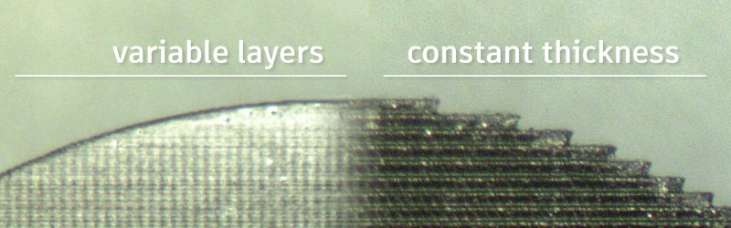
The basic idea behind VariSlice is to print vertical walls at a maximum layer height, while very shallow angles – the top of a sphere, for example – are printed at a very low layer height. That’s simple and obvious; you will never need to print a vertical wall at ten micron resolution, and fine details will always look terrible with a high layer height.
The trick, as in everything with 3D printing, is the implementation. In the Instructable for VariSlice, it appears that the algorithm considers the entire layer of an object at a time, taking the maximum slope over the entire perimeter and refining the layer height if it’s necessary. There’s no weird stair stepping, overlapping layers of different thicknesses, or interleaving here. It’s doing automatically what you’d normally have to do manually.
Nevertheless, the VariSlice algorithm is now one of Autodesk’s open source efforts, just like the Ember resin printer used in the example below. The application for this algorithm in filament-based printers is obvious, though. The speed increase for the same level of quality is variable, but the time it takes to print some very specific objects can be up to ten times faster. Whether or not this algorithm can be integrated into Cura or Slic3r is another matter entirely, but we can only hope so.


Looks very promising. Hopefully, it will be integrated into slicers one day.
The problem is. The patent on it.
doesn’t slic3r allow for variable layer thickness?
http://manual.slic3r.org/expert-mode/variable-layer-height
granted that is a very naive and entirely manual approach so a good script that would automate that is always welcome.
or am i missing something in how this works.
See link in article, misleadingly labeled “that you’d normally have to do manually.”
Slic3r already does this. Well researched Brian.
Oh, this thing?. Couldn’t find where Slic3r changed the layer height in relation to the angle of the top surface. Looks like it’s only doing it by Z-height, not the geometry of the model.
Troll harder.
Love the Troll harder reply to Dimwit/Dimbit!
Don’t let the trolls get under your skin, Brian! Haters gonna hate.
Love HaD, and enjoy your style, warts n all.
They’re not under my skin. My boot, however….
Lol!
Glad to hear, have fun in that case!
what this does is automate the decision making of what one would plug into the slic3r variable layer height function, a very nice feature to have so one doesn’t have to manually add that information to specific models.
but essentially what the printer does physically (and most likely the gcode generated) would be mostly the same in both cases, now look a year into the future and at a specific varislice slicing suite and we might have something really interesting going on.
There is a pull request against Slic3r that adds automatic, variable layer height:
https://github.com/alexrj/Slic3r/pull/1386
Already detects the angle it’s building at, to decide whether it needs support material.
https://github.com/alexrj/Slic3r/blob/3700950474583e6c64163fab848a831cdcfbf44e/lib/Slic3r/Print/SupportMaterial.pm
Doesn’t directly drive the layer height, no.
https://github.com/alexrj/Slic3r/pull/1386
Actually… :D
Looks like the algorithm would be a lot faster if they did a binary search for the right layer thickness. They probably do that, but showed the silly “try every thickness” approach to avoid cluttering up the explanation.
Jose, you’re correct. That would be faster. We used the more naive approach because (1) it was super simple to code and (2) believe it or not, scanning through the triangles is one of the fastest parts of the workflow in the current state. Slicing the STL and some other post steps (not mentioned in the video, but described in the Instructable) take much longer. Right now scanning through all the triangles of a STL with ~100,000 facets takes only a couple of seconds.
I hope they didn’t spend too much of their budget on those audio special effects⚾️????.
This is awesome. It could have been done many different ways. The fact they chose this way is something the whole community will appreciate. It puts a friendly face on a company that hasn’t been as hacker friendly as it could have been. Very nice inclusion of the prior art related to this. Just because something has been considered before doesn’t mean it was done well before.
So you slice the STL model at 5um resolution, then analyze the model (not the slices!) to determine which slices to use? Needlessly convoluted data flow, if you ask me.
Either analyze the slices themselves (XOR with dilation/erosion, doesn’t resolve finer than 1 pixel; seems it should be just enough, but I haven’t done much with morphological operations on grayscale images) or analyze the model first and then slice only the layers you’ll actually use.
I’m pretty sure they lied for the sake of explanation, but you can obviously go way faster than they show on the video.
Scan all the triangles, and note their perfect wanted slicing thickness (by checking the slope wrt Z axis) and their Z span (Zmin,Zmax), then you merge all the spans by keeping the finest wanted slicing thickness. You can even map/reduce it because the merging operation is commutative.
Maybe they didn’t, and they’re looking at Hackaday comments for ways to optimize their algorithm before submitting the patent. DUN DUN DUUUUN
platsch has this published apparently as his master’s thesis: http://www-rp.me.vt.edu/bohn/projects/sabourin/thesis.pdf
Back in 2013.
https://github.com/alexrj/Slic3r/pull/1386
Maybe so, except I wasn’t referring to the video — I was going off the step-by-step instructions in the Instructable.
Don’t get me wrong — the way it’s apparently done is totally a hack, and thus belongs on hackaday. Given that it is, for whatever reasons, better, easier, and/or faster to make the slicing decisions from the STL file, this approach makes perfect sense for a proof of concept — you don’t touch the slicer code, just add a separate script to rejigger the output.
But once you’ve got it working (and reported to hackaday), the next step should be either to integrate the whole mess in the slicer, or better yet patch the slicer to support variable layer thickness, and convert your program to a preprocessor that provides the slicer with layer thickness information.
This could be combined with a smarter version of the ‘Infill every n layers’ in Slic3r so that the infill layer height was maximised while the perimeter heights change.
Is this only for the Ember, or can it be converted to gcode for all other printers?
We are doing this about two years (https://www.instagram.com/p/BMjpH1hgjH4/?taken-by=customcnc)