An exciting development over the last few years has been the arrival of extremely cheap instrumentation modules easily bought online and usually shipped from China. Some of them have extremely impressive paper specifications for their price, and it was one of these that caught the eye of [Carol Milazzo, KP4MD]. A frequency counter for under $14 on your favourite online retailer, and with a claimed range of 500 MHz. That could be a useful instrument in its own right, and with a range that significantly exceeds the capabilities of much more expensive bench test equipment from not so long ago.
Just how good is it though, does it live up to the promise? [Carol] presents the measurements she took from the device, so you can see for yourselves. She took look at sensitivity, VSWR, and input impedance over a wide range, after first checking its calibration against a GPS-disciplined standard and making a fine adjustment with its on-board trimmer.
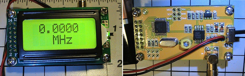
In sensitivity terms it’s a bit deaf, requiring 0.11 Vrms for a lock at 10 MHz. Meanwhile its input impedance decreases from 600 ohms at the bottom of its range to 80 ohms at 200 MHz, with a corresponding shift in VSWR. So it’s never going to match a high-end bench instrument from which you’d expect much more sensitivity and a more stable impedance, but for the price we’re sure that’s something you can all work around. Meanwhile it’s worth noting from the pictures she’s posted that the board has unpopulated space for an SPI interface header, which leaves the potential for it to be used as a logging instrument.
We think it’s worth having as much information as possible about components like this one, both in terms of knowing about new entrants to the market and in knowing their true performance. So if you were curious about those cheap frequency counter modules, now thanks to [Carol] you have some idea of what they can do.
While it’s convenient to buy a counter module like this one, of course there is nothing to stop you building your own. We’ve featured many over the years, this 100MHz one using a 74-series prescaler or this ATtiny offering for example, or how about this very accomplished one with an Android UI?


The cheap equipment from China, no matter what it is, is a double edged sword. You get the promise of something that works, and you think “how bad could it be?”. But when you actually get it, you are getting compromises that you’d never have made on your own. Stuff that works, but only marginally. Kits that are missing components or have been substituted for lesser or incorrect parts. Some of this stuff isn’t designed to be used for its intended purpose. It’s designed to be sold. That being said the quality can be very good, and if you’re okay with marginal, there can be very good deals. I won’t start on the documentation issues.
For example I bought a Chinese tablet for $50 with what looked like reasonably good specs. When I got it, it was listed at customs as being worth $25 and had an invoice to match. So I paid way, way too much. It turns on, it does Android-like things, and works. But it’s awful. Full review on the piece of junk here, if anyone is interested: http://miscdotgeek.com/h701-tablet-review/
I read your review but in all honesty can’t find why you’re so negative about the device.
In all likelihood, the battery worked fine from the first time you turned on the device. But the li-ion / lipo fuel gauge needed a few hours of runtime to calibrate. No full cycles needed there. Also, 2hr20m of video streaming sounds fine for a device advertised with a battery life of 3 hours. Those specs are always based on best-case scenarios such as minimal brightness and minimal load.
Noise canceling is not advertised for this unit, so I don’t see why you’d expect that function. Neither is Bluetooth. Neither is a good quality camera. The charger has, according to you, a good enough build quality.
As for the price, the fact that these units go for $25 in quantities of 10.000 does not mean you should expect to pay $25 shipped for a single item. $50 sounds very reasonable. Besides, we all know why it was only listed as being worth $25 on the customs declaration.
Chinese suppliers will often put a lower price on an invoice and the customs sticker without telling you even if you paid more.
Don’t knock it, they’re doing you a favour because they’re saving you a customs duty bill.
Yeah, the invoice price is often much lower than what the items are worth to avoid customs charges. I have had a camera lens listed as something like $11 (which was a massive under-price) but customs suspected it was worth more so they contacted me before releasing it.
Frequency counters are only as good as their clock reference.
Too bad that this one uses a 20MHz crystal. You can get used 10MHz OCXOs for cheap on ebay, but 20MHz ones are rather expensive. So you’d have to use an additional PLL, which adds jitter and phase noise.
I have several used 10MHz OCXOs, and they’re pretty good, compared to a 10MHz rubidium frequency standard.
They’re power hungry, though. Nothing you’d want to power from a 9V battery.
A 20MHz TCXO might be a good upgrade. They’re affordable, but usually only precise to about +/- 2ppm.
Is some jitter and phase noise caused by a decent pll really an issue for something as mundane as a simple frequency counter?
Yes. It will make the lower significant digits jump all over the place, effectively reducing the usable resolution.
Averaging to get the resolution back will reduce the display rate/increase the latency.
If your PLL has enough phase noise to cause your frequency counter to jump by 100Hz (the lowest readable digit on this counter) you are doing some very wrong. Frankly so long as it is being used at a reasonably constant temperature the simple crystal it has should be fine with occasional calibration if you need the 7th digit to be dead nuts on.
Very true. For $14 you don’t expect much though.
Do you mean a PLL to double it? Why not just a simple passive diode frequency doubler followed by a buffer amp?
http://www.amalgamate2000.com/radio-hobbies/radio/doubler.GIF
No PLL jitter.
That’s what I was going to suggest, though not the specific circuit. There are good reasons to use PLLs at times, but simply doubling something, especially in this situation, cm use a multiplier. After all, that was the standard for all VHF transmitters before a certain time.
Michael
And of course there are other methods utilizing the delay through buffer gates or even just an RC delay into an XOR gate.
http://www.electro-tech-online.com/attachments/xor_doubler-gif.1068/
Just double the 10MHz OCXO to 20MHz and filter.
Might be simple as:
A single 1n4148 connected as a shunt at the osc output, 22pF shunt cap, 20MHz crystal in series, a second 22pF shunt after it and the output fed to the MCU clock input pin.
Or that fancy doubler that Steve Greenfield linked to and add the crystal filter after that if the output is not clean enough.
It looks like it’s a balanced design so the fundamental should not be terribly strong, especially with matched diodes.
Fancy doubler? Hardly. The first transformer is just a toroid with three windings, two connected as a centertapped secondary. I might add a capacitor on the 2nd transformer to resonate it at 20MHz, then a buffer like a 4049 or 4050.
In my case I had a need for exactly this sort of thing’and built my own. It takes a 10 MHz reference input (which I have in spades since I sell GPSDOs on Tindie) and runs an ATTiny directly from that. Timer 1 runs at the system clock and the rising edge of the input goes into the ICP pin so the firmware can count the exact number of clock cycles between each. Most of the pins of the Tiny go to an LCD.
From there the firmware balances averaging against latency and resolution. My goal was around a PPM of usable resolution, and I basically got there (the reference had a 8×10^-11 ADEV).
What’s the working frequency range for the one you built? Do you sell it on Tindie as well?
The working frequency range is up to 100 kHz, but I needed it specifically to measure 16.384 kHz from my Crazy Clock calibration code. It is/was a quick-n-dirty job to solve an urgent instant problem. I haven’t gone back and really scrutinized the design for productization. If nothing else, there’s absolutely no input signal conditioning. I needed to measure a LVTTL square wave, so none was required. The other issue is that because the input reference is the controller’s execution clock, it misbehaves spectacularly whenever the reference is disturbed in any way. While the AVR timers can take external reference inputs, they can’t use inputs that are more than half the execution clock. To do this *right*, you’d need to use a controller with more like a 100 MHz execution clock and have one of its internal timers get clocked from the reference. It’s not that you need the controller to run spectacularly fast, it’s that you need to be able to count exactly how many rising edges of the reference there are between rising edges of the test signal, and you can’t tolerate huge amounts of quantization error caused by a relatively slow sampling clock.
I did go to the Hackaday supercon this year and attended the PIC workshop. That’s expanded my microcontroller universe just a little. Perhaps there’s a PIC that has a more versatile counter/timer that could be used to solve this.
There are a couple other frequency counters on Tindie, but so far as I am aware, none of them can operate from an external reference. That sort of stuns me a little, as the single most impactful thing you can do to make a frequency counter more accurate is to make its reference more accurate and stable.
The sensitivity is not that critical in my opinion. It depends what you are measuring of course, but you can add a simply block amplifier if needed.
It seems to me that high sensitivity would be more problematic, as noise rejection would be more difficult.
Simple enough to add a switch.
well you know great job i guess but testing one module doesn’t really prove anything or help anyone looking for a supplier. even if you order the same ‘part’ from the same supplier its not necessarily going to be the same thing
I purchased one of these little frequency counter from Aliexpress for about 10UKP.
It doesn’t work at all.
Using a new 9V PP3 battery, I switch the unit on and get a nice green backlit screen with no display.
Pretty useless.